TPL5110 Nano Power Timer Hookup Guide
 Elias The Sparkiest
Hardware Overview
Power and LiPo Battery
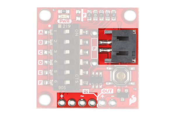
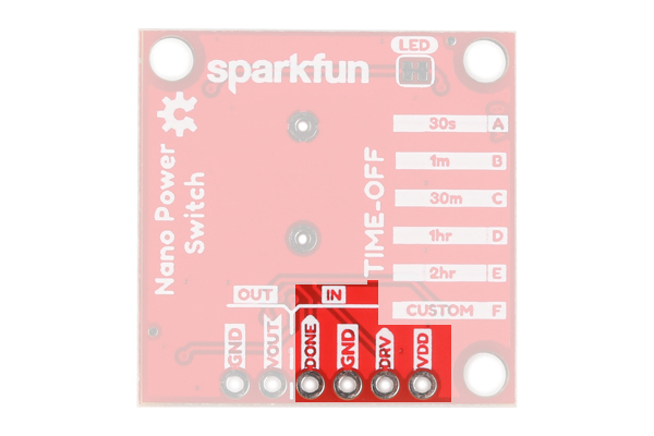
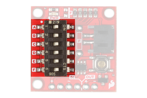
The Nano Power Timer can handle voltages between 1.8V - 5.5V and current up to 1.1 Amps. There are two options when connecting power to the Nano Power Timer. The first and more obvious option is the on board LiPo Battery Connector. The second is the VDD and GND pins on the five pin header underneath the IN label (short for INPUT). The power you provide to the INPUT side will flow out the OUTPUT side to power your microcontroller or project. If your using a LiPo battery, then do not attach another power source to these pins.
 |
 |
| Top | Bottom |
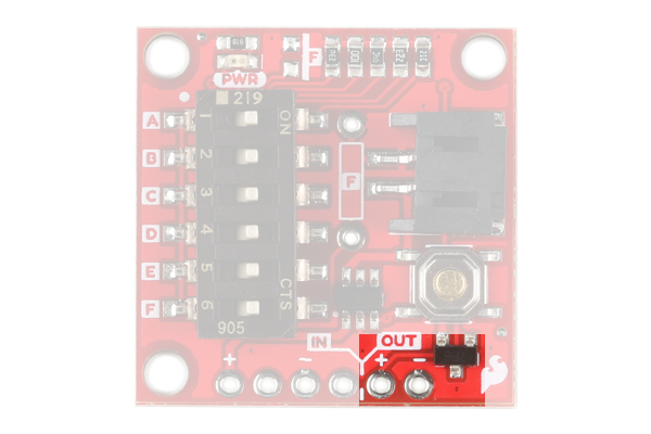
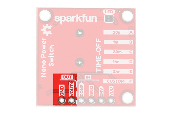
The OUT (OUTPUT) power is labeled VDD_OUT and GND. These pins will go to the board or project that you are powering.
 |
 |
| Top | Bottom |
Timer and Delay Switch
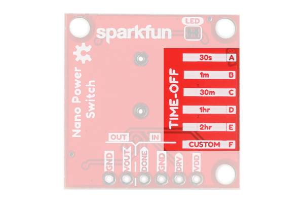
The Nano Power Timer's main function is to turn your microcontroller on after a set amount of time, continuously. The board has a six DIP switch that controls this time by changing resistance to the timer pin on the IC. To the left of the switch are five letters labeling each switch. On the underside of the board are these letters and the amount of time that is set when the corresponding switch is flipped.
 |
 |
| Top | Bottom |
This time is set when the board is powered up, so cycle power after you select your time. Check the table below to find a time suitable for your project.
| Timer | Switch | Resistance |
|---|---|---|
| 30 s | A | 16.2 kΩ |
| 1 min | B | 22 kΩ |
| 30 min | C | 93.1 kΩ |
| 1 hr | D | 124 kΩ |
| 2 hr | E | 169 kΩ |
| Custom | F | Custom |
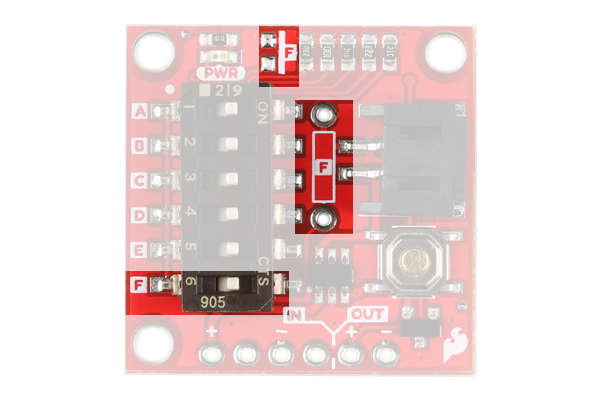
If you're time is not listed then we've left two additional pads for a custom time: one SMD and the other PTH. These two spaces are labeled with F on the product and their corresponding switch is labeled the same. If you decide to use them both at the same time their resistance is in parallel so make sure to calculate accordingly.
More Timer Options
You are not limited to the times that are represented on the silk. Ignoring the Custom switch option, there are 26 possible combinations of switches aside from the five printed on the board that yield times from three seconds up to 15 minutes. The chart below gives you the combination of ON resistors, their combined resistance, and their approximate time. A few redundant resistances were ommited.
| Timer | Switch Combo | Resistance |
|---|---|---|
| 2-3 s | A+B+C+D+E | 7.579 kΩ |
| 3-4 s | A+B+C+D | 7.933 kΩ |
| 4 s | A+B+C | 8.470 kΩ |
| 5 s | A+B+E | 8.844 kΩ |
| 6 s | A+B | 9.329 kΩ |
| 10 s | A+C+D+E | 11.563 kΩ |
| ~12 s | A+C+D | 12.407 kΩ |
| ~13 s | A+C+E | 12.742 kΩ |
| ~15 s | A+D+E | 13.225 kΩ |
| ~18 s | A+C | 13.774 kΩ |
| ~19 s | B+C+D+E | 14.243 kΩ |
| 20 s | A+D | 14.341 kΩ |
| ~22 s | A+E | 14.790 kΩ |
| ~25 s | B+C+D | 15.546 kΩ |
| ~28 s | B+C+E | 16.075 kΩ |
| 32 s | B+D+E | 16.852 kΩ |
| 35 s | B+C | 17.754 kΩ |
| 40 s | B+D | 18.707 kΩ |
| ~45 s | B+E | 19.479 kΩ |
| ~5 min | C+D+E | 40.400 kΩ |
| 8 min | C+D | 52.995 kΩ |
| ~12 min | C+E | 59.694 kΩ |
| 15 min | D+E | 72.033 kΩ |
Some of these times are approximate, but I have provided a Python script in the resources below to help you calculate what your exact time is. This will differ by small margins for each board due to the tolerance of the resistors.
Additional Timer Options From Datasheet
Below is the list of available times from the datasheet that are not included in the charts above. Of note are the timer options in the millisecond range. You can access these times by taking advantage of the two empty resistor pads on the Nano Power Timer.
| Timer | Resistance |
|---|---|
| 100 ms | 500 Ω |
| 200 ms | 1000 Ω |
| 300 ms | 1500 Ω |
| 400 ms | 2000 Ω |
| 500 ms | 2500 Ω |
| 600 ms | 3000 Ω |
| 700 ms | 3500 Ω |
| 800 ms | 4000 Ω |
| 900 ms | 4500 Ω |
| 1 s | 5.20 kΩ |
| 2 s | 6.79 kΩ |
| 7 s | 9.71 k Ω |
| 8 s | 10.18 kΩ |
| 9 s | 10.68 kΩ |
| 30 s | 16.78 kΩ |
| 50 s | 20.047 kΩ |
| 2 min | 29.35 kΩ |
| 3 min | 34.73 kΩ |
| 4 min | 39.11 kΩ |
| 5 min | 42.90 kΩ |
| 6 min | 46.29 kΩ |
| 7 min | 49.38 kΩ |
| 9 min | 54.92 kΩ |
| 10 min | 57.44 kΩ |
| 20 min | 77.57 kΩ |
| 40 min | 104.67 kΩ |
| 50 min | 115.33 kΩ |
| 1 hr 30 min | 149.39 kΩ |
Push Button
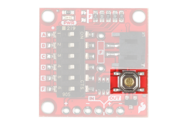
The push button on the product will manually begin the timer. This allows you to test the timer and your project which should send an OFF signal to the Done pin.
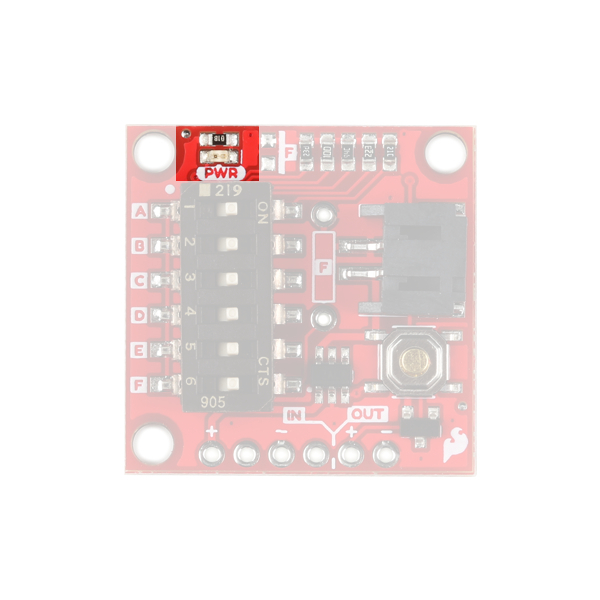
LED
There's a single red power LED on the topside of the product which indicates power is being supplied to the OUT pins. If you want to disconnect this LED, simply cut the trace between the jumper on the underside of the board labeled LED.
|
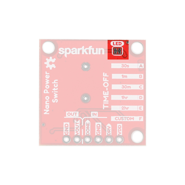 |
| Power LED | Power LED Jumper |
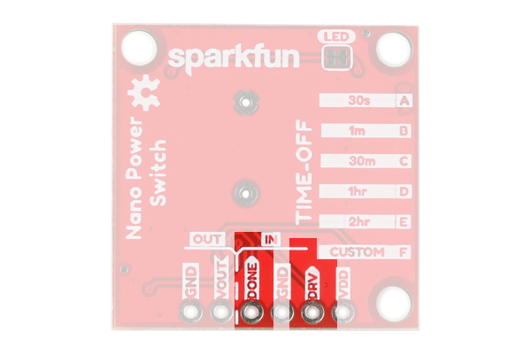
Header
Next to GND is the DONE pin that tells the product to turn your microcontroller or project off. To do this, your microcontroller or project will need to send a digital signal from LOW to HIGH to this pin. Finally, the DRV pin is active high and will start the timer of your project when the pin receives a HIGH signal. This is the same function as the on board push button. Not very many people will want to attach a different button, but if you wanted to, this would be the place.
How Do I Check the Exact Time?!
I've provided a simple Arduino sketch below to calculate the exact timing of the timer setting. You'll attach the VOUT pin to a digital I/O pin on your microcontroller and the sketch will start its timer when the power is high and end the timer when the power is off.