Contributors:
 Elias The Sparkiest
 Hardware Hookup
⚡
Warning! When powering a microcontroller to the Arduino via USB, you will need to disconnect the TPL5110 from the Arduino's power input. The conflicting power sources will damage the TPL5100. You may want to consider adding a
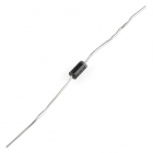
Schottky diode betwen the TPL5110's output voltage and the microcontroller's voltage input.
COM-10926
Schottky diodes are known for their low forward voltage drop and a very fast switching action. This 1A 40V Schottky diode is …
Note: Depending on your microcontroller, you may need to add a pull-down resistor on the Done pin. We found that the SAMD21 and SAMD51 boards required a
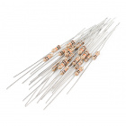
pull-down resistor to trigger the TPL5110's Done pin reliably.
PRT-14491
These are your run-of-the-mill 1/4 Watt, +/- 5% tolerance PTH resistors. Commonly used in breadboards and other prototyping a…
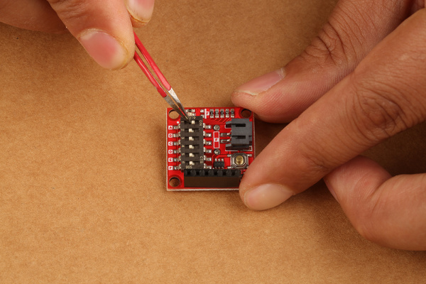
We're going to power a RedBoard Turbo with a 3.7V LiPo Battery and set it to a 14 second delay. By default, the board comes with every switch flipped to the ON position which is 3 second timer. To set the timer to 14 seconds, we'll turn some switches to the ON position and others to the OFF position. I used tweezers because the switches were too small for my hands.
To get a 14 second delay switches 'A' + 'D' + 'E' must be flipped ON, and the other swtiches flipped OFF.
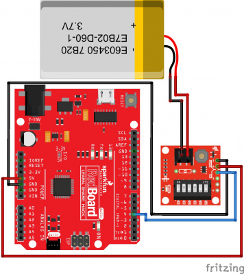
Next solder a 6 pin header of your choice to the Nano Power Timer. After the six pin header is soldered to the Nano Power Timer, plug in three wires into the female header as follows:
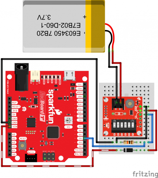
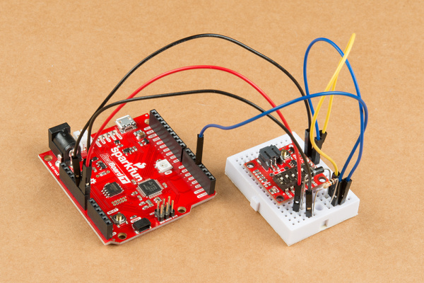
We'll use a Schottky diode to protect the TPL5110 when the RedBoard Turbo is connected to a computer when prototyping and uploading code. Additionally, we'll add a pull-down resistor on the Done pin. Depending on your microcontroller, you may not need resistor. After wiring your circuit together, you may have something similar to the image below without the battery connected.
Let's move onto the code.
Note: If you are looking to reduce the number of components used with the TPL5110 and a microcontroller, you could solder wire directly to the PTH pins, remove the pull-down resistor, and Schottky diode. Just make sure to disconnect the VOUT pin whenever you are connecting a USB cable to your microcontroller to upload.
