Thumb Joystick Hookup Guide
 MikeGrusin,
  bboyho
Hardware Overview: Shield
Below is a top view of the shield before any component is soldered.
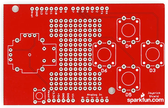
Joystick - On the left of the board is the footprint for the thumb joystick. The potentiometers are connected to analog pins A0 and A1. The "select" button for the joystick is connect is connected to pin 2.
Prototyping Area - The center includes general plated through holes to prototype and solder additional components like a small OLED screen, XBee Explorer, or sensors. You'll need to wire it up to the respective pins depending on your project.
12mm Buttons - On the right are locations for four 12mm momentary pushbuttons. Up is connected to pin 4, right to pin 3, down to pin 5, and left to pin 6.
Edge Pins - The board was designed for the original Arduino Uno footprint so you'll see the standard headers on the edge of the board.
Note: From the inception of Arduino until some time in 2012, every Arduino had the same standard footprint: two 6-pin headers on one side, two 8-pin headers on the other. Lately, though, Arduinos have been transitioning to a new shield-header layout, called the R3 footprint. This layout has a 6-pin and 8-pin headers on one side, and an 8-pin and 10-pin on the other. While this board uses the old style version, it still has the same functionality when stacked on an Arduino Uno R3 footprint.Reset Button - Just beside the reset pin is the location for the mini push button to reset an Arduino when stacked on top.