Thumb Joystick Hookup Guide
 MikeGrusin,
  bboyho
 Hardware Assembly: Shield
Before assembling the shield, make sure that you have all the components needed to solder the board together.
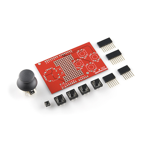
If you ordered a kit, you should have the following components included.
- 1 x Thumb Joystick (COM-09032)
- 1 x Joystick Shield PCB (DEV-09490)
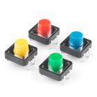
- 4 x Momentary Push Button Switch - 12mm Square (COM-09190)
- 2 x 8-pin Arduino Stackable Header (PRT-09279)
- 2 x 6-pin Arduino Stackable Header (PRT-09280)
- 1 x Mini Push Button Switch (COM-00097)

All parts present and accounted for? Great, let's start to put the shield together.
Insert Thumb Joystick and Buttons to Shield
Before I start to solder parts into place, I like to do a "test fit" of the kit components. This allows me to check that everything fits as expected plus it's fun. Just work through the rest of these instructions carefully putting the components into place but don't solder anything. This is entirely optional.
Once you've done a test fit, you can pull the components out with care and then put the shield together for real!
Soldering Tips
If this is your first time soldering you'll probably want to check out our introductory soldering tutorial first. Read the guide and you'll pick up some good tips that will help your first soldering experience go more smoothly.
How to Solder: Through-Hole Soldering
Below you'll find a suggested order for assembling the shield, your personal preference might give you other ideas on how to proceed and that's fine too. When no order for assembling is provided, soldering the smallest components in first is a good rule to follow. Just make sure all the pieces go in the right place and in the correct orientation.
If you don't have a PCB vise then you might want to put the header pins in before the thumb joystick — that way you can rest the PCB on the headers as you solder the pins. (In fact, you might want to do this even if you do have a vise.)
Another approach to consider is to attach the headers first so you can test each component is working after you add it.
Alright, let's start with...
Mini Push Button Switch
The mini push button resets the main Arduino board — it's present because once the shield is connected to the Arduino, it's difficult to access the normal reset button.
Ensure you're looking at the top of the PCB — the top is where the components sit — it will have the "sparkfun.com" text and logo on it.
Begin by pushing the four legs (or leads) of the button into the correct location on the PCB as shown in the photograph below. It sits just below the word "Reset" on the PCB. The button can be orientated in four different directions with the legs pointing down but only two of them are correct — you shouldn't need to apply much force to seat the push button in the holes. See the next closeup image for a better view of how the button should sit.
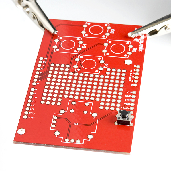
You can see more clearly below that the legs splay out slightly. There's two pairs of legs on opposite sides of the body — one pair should sit in the set of holes close to the edge of the PCB while the other pair should sit on the opposite short-edge side of the white rectangle marked ("silk screened") on the PCB.
If you bend one of the legs too much gently move it back into place — but don't do this too often or the metal will break from metal fatigue.
With enough room below the PCB for the legs to extend apply pressure to the top of the push button so the plastic bottom sits on the PCB — this allows the PCB to take most of the force when you press the button rather than the thin metal legs.

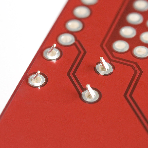
Next turn the board over and you should see those cute little legs pointing through the holes in the PCB. If they don't extend as far as shown in this picture check you have the orientation correct and then apply a little more pressure to pop the legs through. The button shouldn't fall out of the holes when you turn the PCB upside down.
Now it's time to solder the first leg — it doesn't matter which of the four you start with — but ensure the plastic bottom of the button is still flat against the PCB. Apply heat with the soldering iron simultaneously to the leg of the button and the pad (the circle of track around the hole) on the PCB then carefully feed a little piece of the solder into the joint formed between the soldering iron, pad, and component leg. Then remove the solder wire and then the soldering iron — in that order.
Once you have completed one leg, again check the bottom of the button is touching the PCB and then solder the diagonally opposite leg as well. Soldering the legs in this order ensures the button sits well and you can solder the two remaining legs without needing to double-check if the button is still sitting correctly.
When you have soldered all four legs of the button it should look something like the photo below:
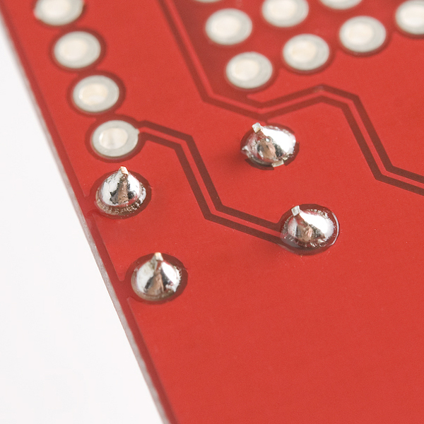
If you like, you can flip the board back over and give the mini push button a triumphant press and show it to your friends.
Push Buttons
It is now time to attach the four larger push buttons to the shield. These are the "action" buttons of your joystick shield and you can use them to control the actions of a character on screen, perhaps causing the character to shoot, punch or arrange flowers as the mood strikes. ("Flower Arranger II : This time it's Perennial!")
You'll notice the method we use is very similar to the approach we took with the mini push button — this is because the buttons are almost identical in construction apart from their size.
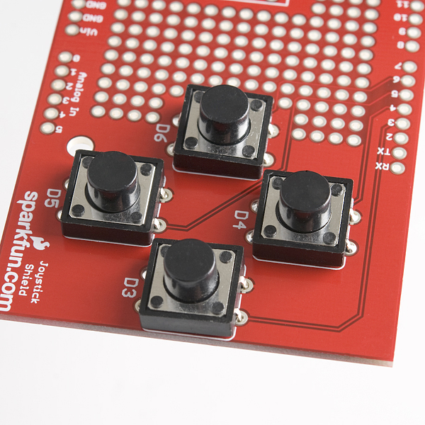
First, insert the legs of the four buttons into the holes on the PCB — their orientation should mean the edges without legs cover the white silk screen lines above and below the white silk screen circles. For each button ensure all four legs are inside their respective holes before applying pressure to the top of the button to push the legs through to the other side — if you're not careful you can bend one or more of the legs under the button by accident. If you do bend one of the legs under, remove the button and use a small screwdriver or pair of pliers to straighten the bent leg enough that it will again sit in the correct place to fit through the hole.
I suggest putting all four buttons into place before soldering them because the legs will prevent them from falling out when you flip the board over and it's nice to be able to get into the flow of things and solder all the joints at one time. But if you prefer to solder each button in place before adding the next that should work okay too.
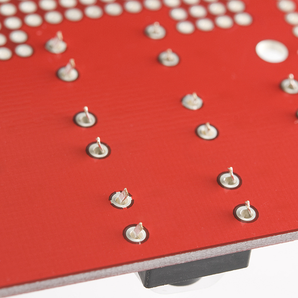
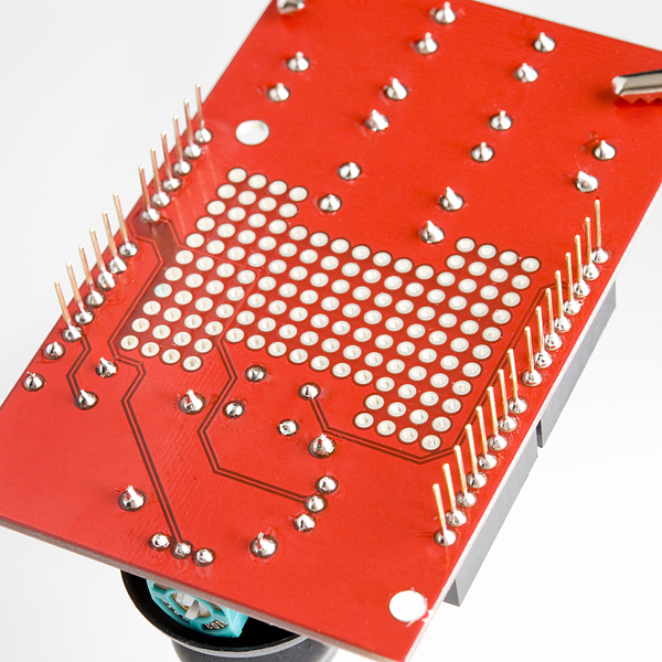
You can now flip the board over and see the push button legs all poking through in a manner resembling the view of the pool during a synchronized swimming competition.
Once again it's time to solder the first of the button legs. My suggestion is to start with the button closest to the middle of the board and work left to right and down from there so you don't have to move the soldering iron over already soldered joints. Again the order isn't critical though.
As before, it doesn't matter which of the four legs of the button you start to solder — but remember to ensure the plastic bottom of the button is still flat against the PCB. You may have to hold the buttons from underneath against the PCB as the legs might be a little loose, be sure to touch only the plastic part as the metal part will heat up. Apply the heat with the soldering iron simultaneously to the leg of the button and the pad then carefully feed a little piece of the solder roll into the joint formed between the soldering iron, pad, and component leg. Then remove the solder wire and then the soldering iron — in that order.
Once you have completed one leg, again check if the bottom of the button is touching the PCB and then solder the diagonally opposite leg as well. Soldering the legs in this order ensures the button sits well and you can solder the two remaining legs without needing to double-check if the button is still sitting correctly.
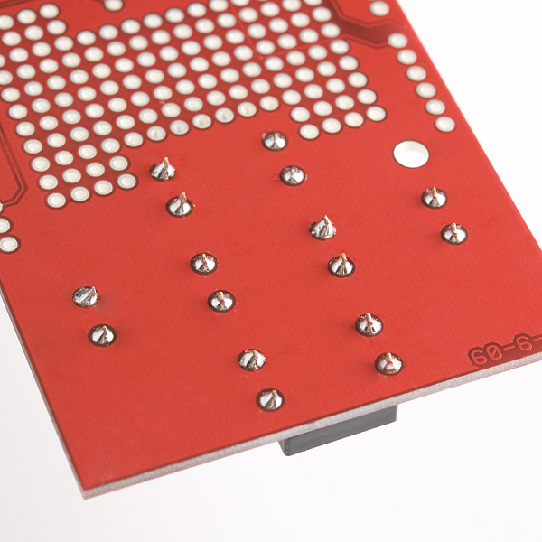
After you've finished all sixteen legs the board should look like this — I hope those swimmers weren't planning on leaving the pool today:
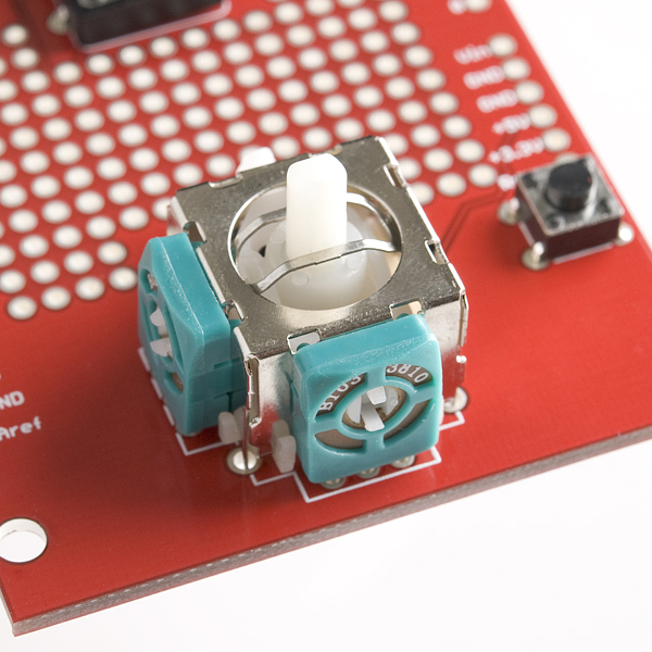
Thumb Joystick
As you may recall from the introduction to this soldering section I suggest you learn from my experience (especially if you don't have a PCB vise) and solder the headers before you solder the thumb joystick. If that's the case, feel free to skip ahead to the headers section and then return to this joystick section.
Ha, I can't believe they fell for that "solder the headers first" trick, can you? Well, joke's on you because it really is easier to solder the headers before the joystick but if you insist, here's how to get the joystick connected. Just remember if you have the headers connected then your board will look a little different to these photos.
You first need to insert the legs of the joystick into the board similar to the breakout board. There's quite a number of legs of different sizes so it pays to be careful pushing the joystick into place.
You'll notice there's a number of sets of legs:
- Four legs for the small mini push button used for the center button functionality. This sits on an outcrop that juts out from one side of the white plastic base and will look suspiciously similar to our reset mini push button. These are quite thin legs.
- Four legs which are thicker than the others and are located at the four corners of the main part of the white plastic base. These legs are structural only and aren't intended to connect to any electrical signals.
- Two sets of three legs each connected to the green/black bodies of the potentiometers used to detect the joystick position in two dimensions.
You might find it easier to remove the black plastic top or "hat" from the joystick first like I have in these photos — just give the hat a gentle tug and it should slide off the center stick. Put the hat to one side so you don't lose it or see if you can wear it as a hat yourself in which case you probably will lose it.
The mini push button legs are the most difficult to get in the correct place so I suggest you line those ones up with the appropriate holes first. Note the whole joystick will only fit in one orientation which has the mini push button facing the center on the PCB. It might help to tilt the base of the joystick slightly so that the two structural legs closest the mini push button fit into their associated holes around the same time as the button legs are in the right place. Then tilt the base level so the remaining legs fit into their proper holes. It's like putting on trousers, there's few things more annoying than getting your leg in the wrong hole — so take your time to make sure everything's where it should be.
If you do bend a leg, first try to see if you can push it gently into position with the head of a small screwdriver, otherwise take the joystick out, straighten the leg and try again — but once again if you do this too often the leg might snap off from metal fatigue.
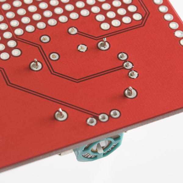
Once you've applied enough pressure to the top of the joystick case all the legs should poke through the bottom of the PCB — the structural legs will protrude further than the others:
You have a couple of options for the order in which you solder the legs but my suggestion is to start with the structural legs:
- Ensure the base is sitting as close to the PCB as possible — it won't sit entirely flush as there are plastic bumps on the base that prevent this.
- Then solder the four structural legs starting with any leg. You can use more solder than you might normally use to provide extra support.
- Check the base is still somewhat flush.
- Solder the diagonally opposite structural leg into place.
- Then solder the two remaining structural legs in any order.
- After the structural legs are in place, I'd suggest soldering the two sets of three potentiometer legs.
Finally, ensure the mini push button legs are through the PCB as far possible and solder the button in place in the same way you've done before.
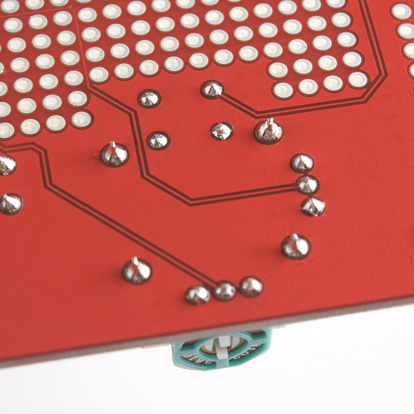
When you're finished your board should look somewhat like this:
If you've already attached the headers you can now flip the board over and reattach the plastic hat to the white center post of the joystick — take note that it will only fit in two orientations as the center post is rectangular. You can now skip to the Completed Solder Joints section.
If you still need to attach the headers you can move on to the next section.
Feel free to pretend you're using the joystick to dock the Apollo before you move on. ("Psssh" thruster noises aren't optional if you do though.)

Headers
Now it's time to solder the headers. You'll notice in these images and the parts list we use the stackable headers which allow an additional shield to be stacked on top of this one. The alert among you will notice however that a standard shield won't fit on top of this shield due to the position of the joystick and even if it did it would obscure at least one of the push buttons.
So what's the advantage of using the stackable headers in this case? It means you can still insert jumpers into the headers to gain access to the unused pins. If you wanted you could also add a custom mini shield on top if you'd like — perhaps with a couple of extra buttons?
If you don't think you'll need this extra functionality you can use standard breakaway headers instead. If you only populate the used pins with headers you can probably still insert jumpers into the other through the holes in the PCB if you need.
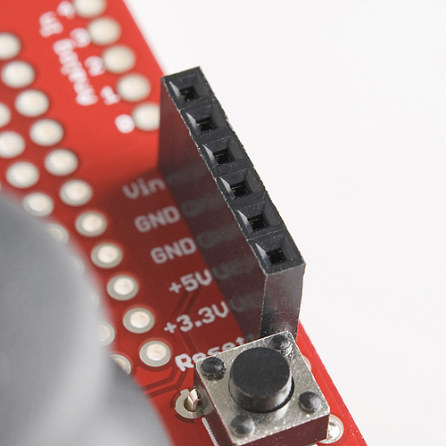
Six Pin Headers
Let's start by soldering the two six pin headers that will supply power and access to the analog pins. First, you can insert one of the headers into the correct location like this:
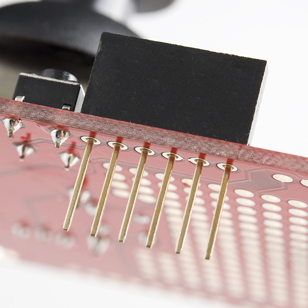
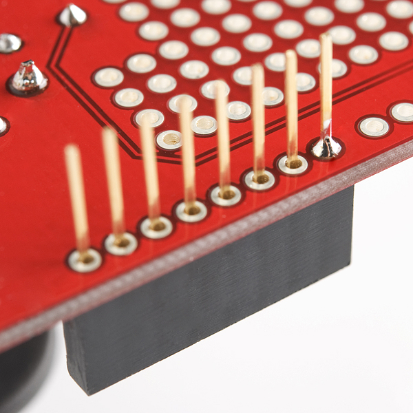
If you don't have a PCB vise then you will probably want to temporarily put one of the 8 pin headers into its location so that the PCB is level when you solder the headers. The headers won't stay in place when you flip the board over so hold them in place when you turn the PCB over to leave the pins sticking upwards.
If you have a PCB vise you might want to hold the header in place like the following photo:
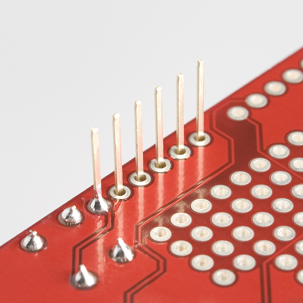
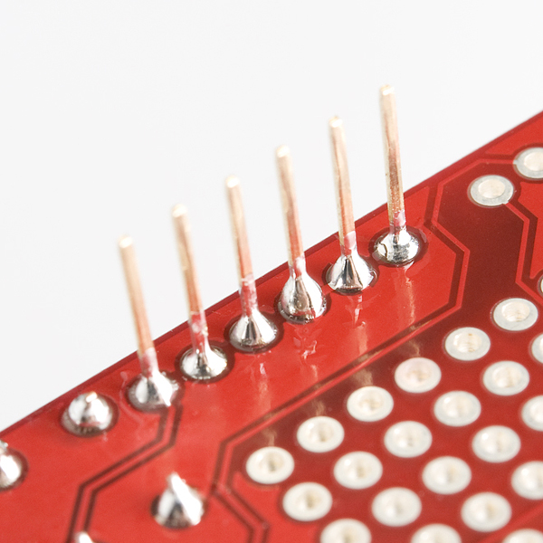
Next solder one of the pins into place. Ensure the header is aligned as parallel as possible to the edge of the board when you do this:
The reason we start with just one pin is because it makes it easier to obtain the correct alignment and fix any mistakes. Once you've soldered one pin, you might want to test the alignment by inserting the shield into an Arduino. Just be careful when you do so because the header's still only held in place with one solder joint.
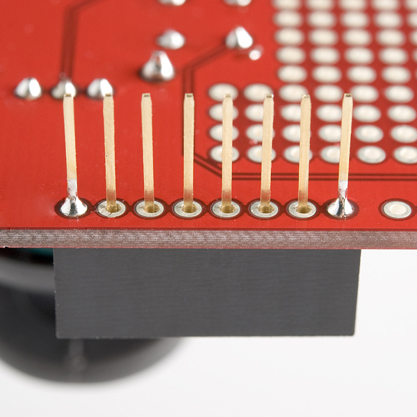
If the alignment of the header isn't quite right, carefully reheat the solder joint and move the header slightly. Don't move it after you've removed the heat however, or you'll end up with a poor joint. Here is an example of checking the header alignment:
Once you're happy with the alignment of the header, you can solder another pin into place — my recommendation is to solder the pin at the opposite end of the header to the first pin you soldered. The reason for this is that once the two end pins are in place, the alignment won't change. I recommend double checking the alignment is still okay again by connecting it to your Arduino again.
Once again, if the alignment's not quite right you can reheat the joint and carefully move the pin.
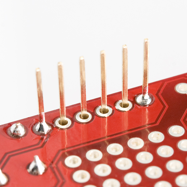
After you've confirmed the alignment you can solder the remaining four pins into place:
At this stage you can repeat these instructions for the second 6 pin header or skip ahead to solder the diagonally opposite 8 pin header. Soldering a 8 pin header now helps to get the alignment right.
Eight Pin Headers
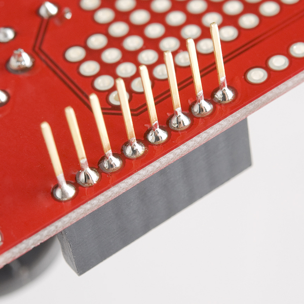
All right class, who can tell me how we're going to solder the 8 pin header..? Yes, you're correct, exactly the same as the 6 pin header except for the last step where we have an extra two pins to solder into place. As before, first we solder a pin at one end and check the alignment:
Then we solder the pin at the opposite end of the header and re-check the alignment:
And finally we solder the remainder of the pins in the middle of the header.
Repeat this for the second 8 pin header and you're done!
Don't forget to go back and solder the last 6 pin header if you skipped ahead. And if you still need to solder the joystick into place you can go back to that section.
Completed Solder Joints
Once you've finished soldering all the components into place your board will look something like this:
Doesn't that red PCB look just spiffy?
Now's the time to double check all your soldering and fix up any problems:
- Do the joints all look shiny and volcano shaped?
- Do you have any "shorts" or "bridges" between joints where you've accidentally connected the two joints with solder? Check out the soldering guide for advice to avoid these problems.
Don't be too fussy though because re-heating and moving the joints is to be avoided if possible.
Completed Shield
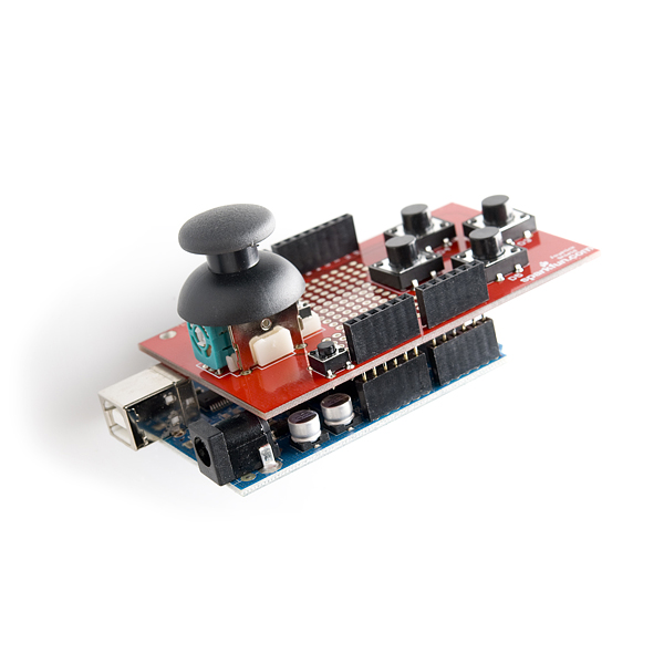
Once you've completed your shield it should look like this.
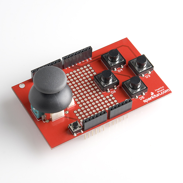
When you are ready, stack the shield on top of the Arduino!
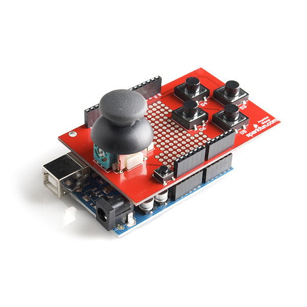
Now it's time to make your joystick shield control something!