Thumb Joystick Hookup Guide
Hardware Assembly: Breakout
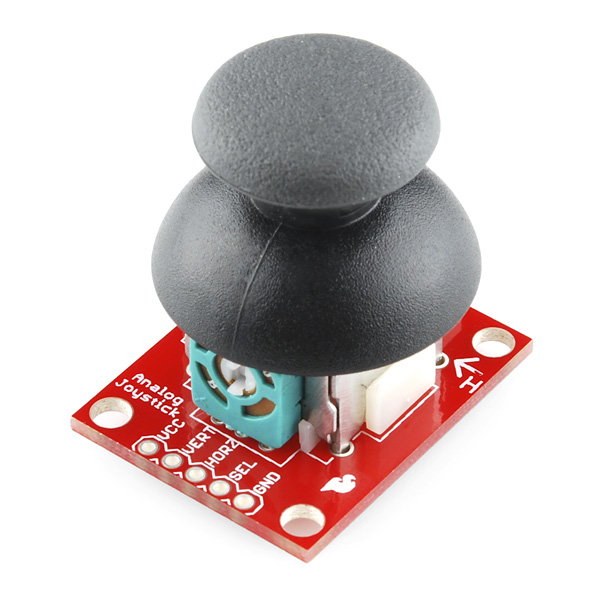
To easily connect to the joystick, you'll need a "breakout board" (the red printed-circuit board, or PCB). You'll need to solder the breakout board to the joystick. Never soldered before? It's easy, check out our tutorial on how to solder. If this is your first time soldering, practice a bit before working on this board. Read the guide and you'll pick up some good tips that will help your first soldering experience go more smoothly.
How to Solder: Through-Hole Soldering
Once this is done, it will be much easier to connect the joystick to your project (you won't have to solder wires to all those little pins). To attach the breakout board to the joystick, follow these steps.
Insert Thumb Joystick to Breakout Board
First, test-fit the breakout board to the joystick. If any pins on the joystick are bent, gently straighten them. The joystick goes into the side of the board with the white outline (not the side with the SparkFun logo). Insert the joystick into the board, matching the white outline, and ensure that all the pins go into their holes (if they don't, you may not have the joystick oriented correctly).
Solder
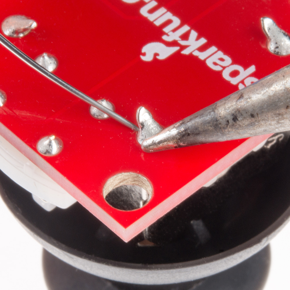
If everything fits OK, carefully solder the pins from the opposite side of the board (the side with the SparkFun logo). Before and during soldering, ensure that the joystick stays tight against the breakout board. There are 14 solder connections to make, including the four posts at the corners of the joystick.
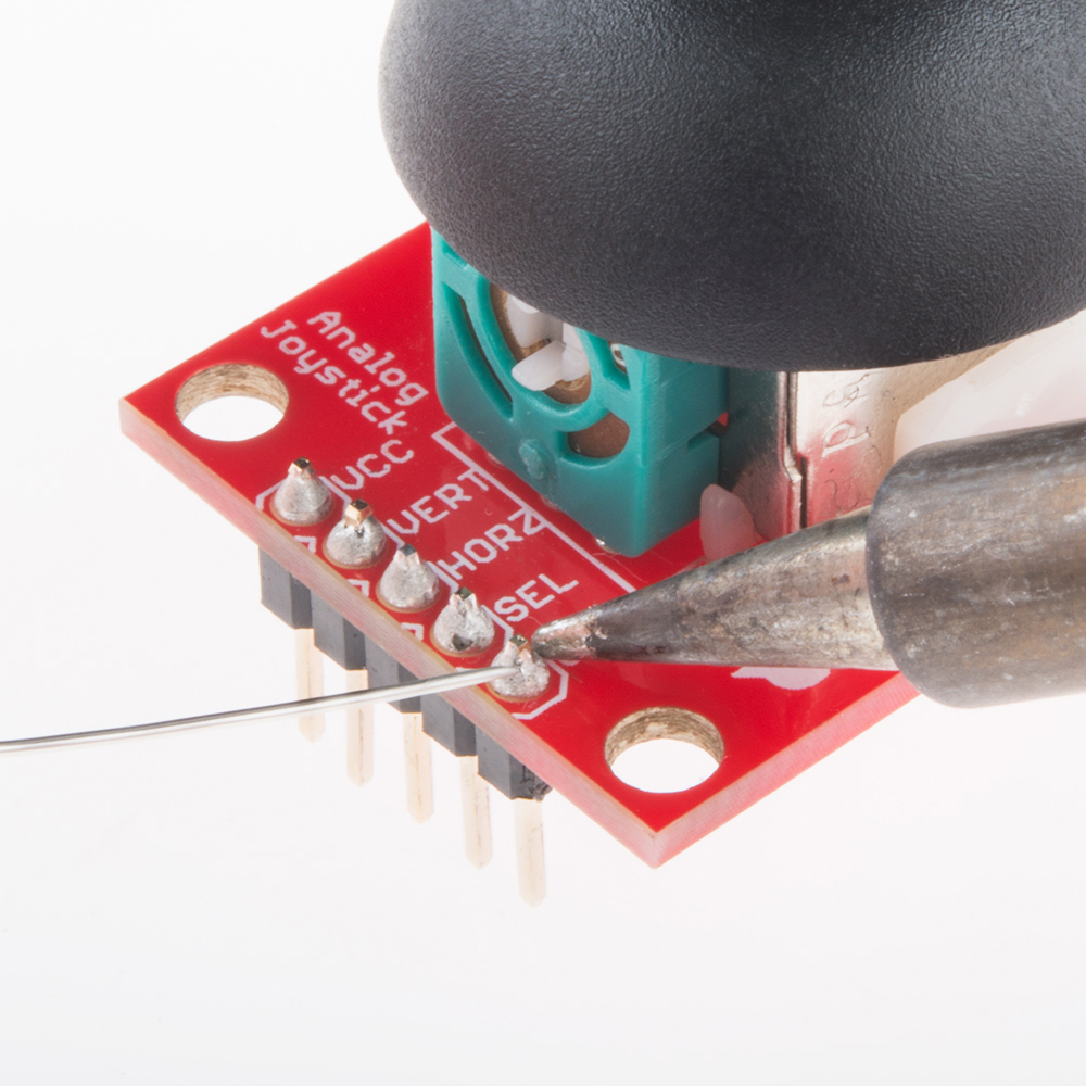
If you'd like to connect a 5-pin header to the board, or solder bare wires to the output holes, you may do that now.
Once you're done soldering, you're ready to use your joystick! If you have not already, insert the cap on the joystick.


