The ClockClock Project
Physical Build
In this section I’m going to be fairly brief as the focus of this tutorial is on FPGA designs and not woodworking.
Click on each of the links below to access and download the project files:
The project first started with trying to figure out how to make one of the clock movements. I needed two stepper motors and a way to connect them to two concentric output shafts.
Originally, I found these super tiny stepper motors on Amazon that measured a tiny 8 x 9.2mm! I designed a piece that had two big gears and two small gears that would press fit onto the motors.
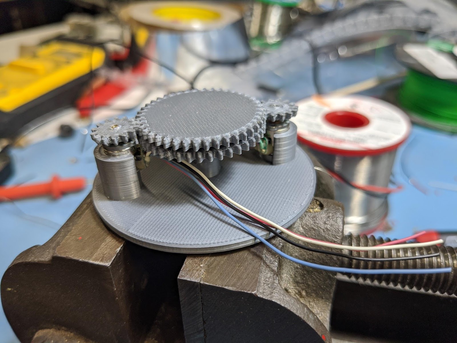
Unfortunately, these little motors just weren’t up for the task of turning the gears. They output only the smallest amount of torque and trying to drive them hard enough to work made them heat up to the point of them melting the 3D printed PLA parts.
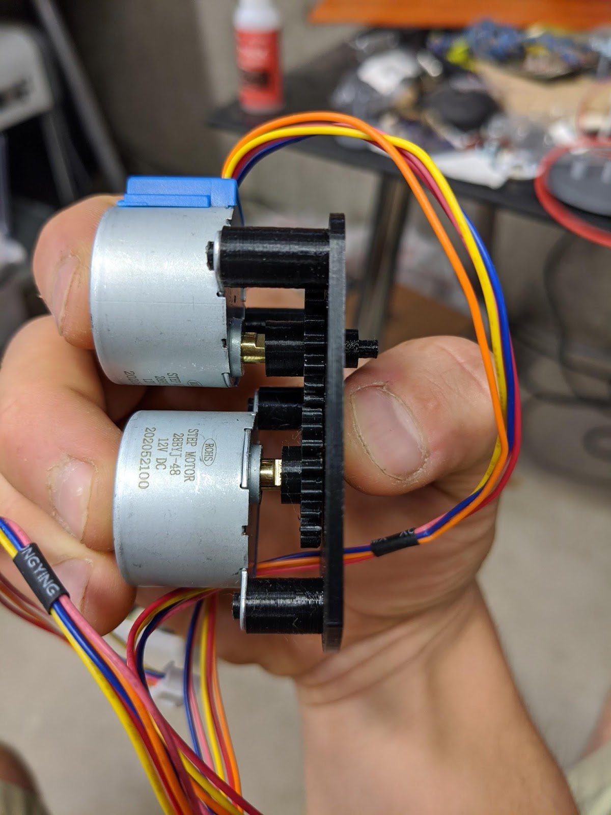
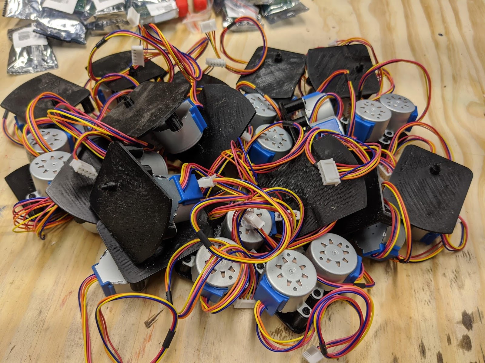
Giving up on these, I ordered a bunch of 28BYJ-48 stepper motors. These are quite a bit bigger but still plenty small for the clock. They also are internally geared and output plenty of torque. The internal gearing also means they have enough internal resistance to easily keep their position when powered off.
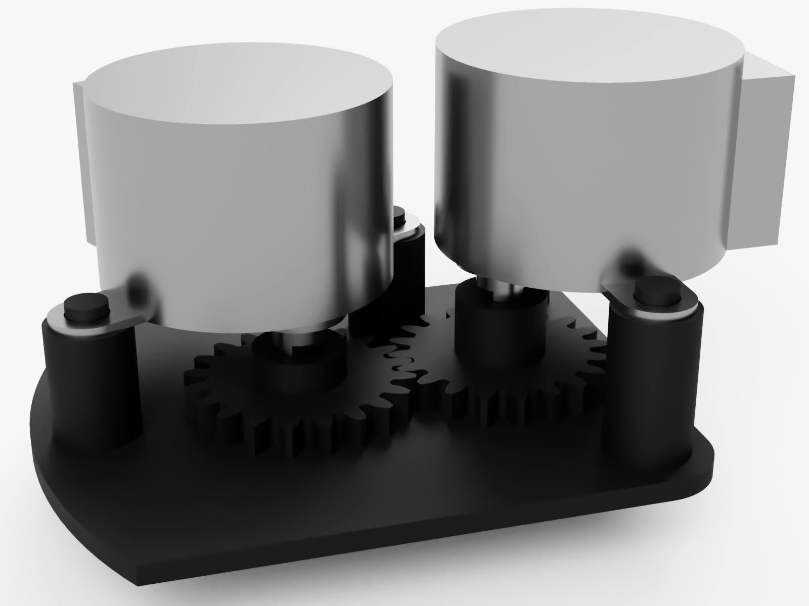
I designed a movement where the minute hand would be directly driven off the motor shaft and the hour hand would be driven via a gear so the motor could be offset to the side.
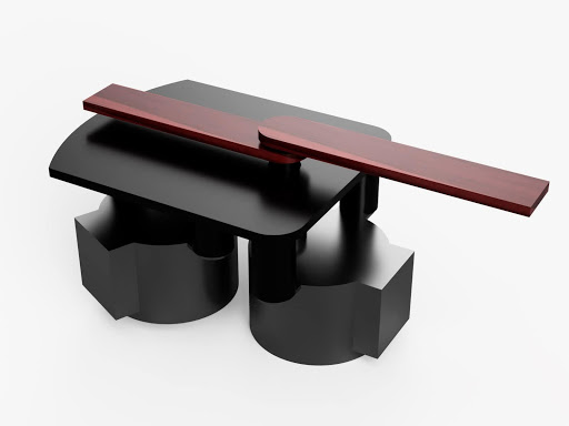
Here are some renders of the design. This first render shows the two output shafts. The center longer shaft connects directly to the motor inline with it. The outer shaft is attached to the gear and that gear is driven by the second motor. The hour and minute hands are friction fit onto these two shafts.

The friction fit allows the hands to be repositioned into a neutral position before the clock is powered on. This is important because even though stepper motors are great for controlling precise positions, they have no way of knowing where they start.
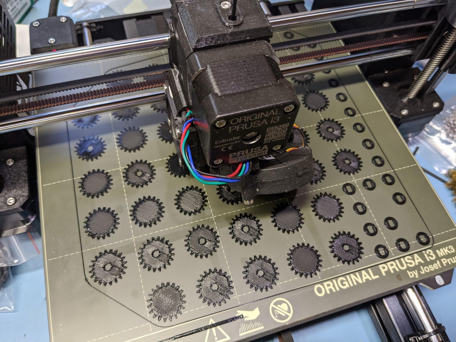
The motors were simply super glued onto the mounting pegs. All the parts were printed on my Prusa MK3S in black PLA.
This is a photo of the first finalized movement I printed and assembled.
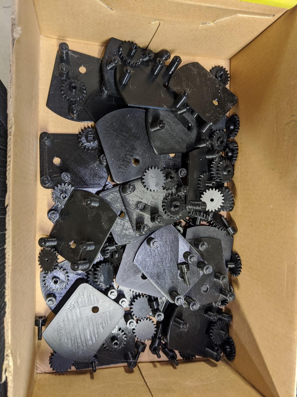
Once I had a working design, I was able to batch out the 24 of these I needed.
The next step was to create the frame. I made it out of two planks of maple. The first plank I resawed into three thinner pieces that I could glue together to make the face.
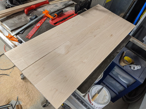
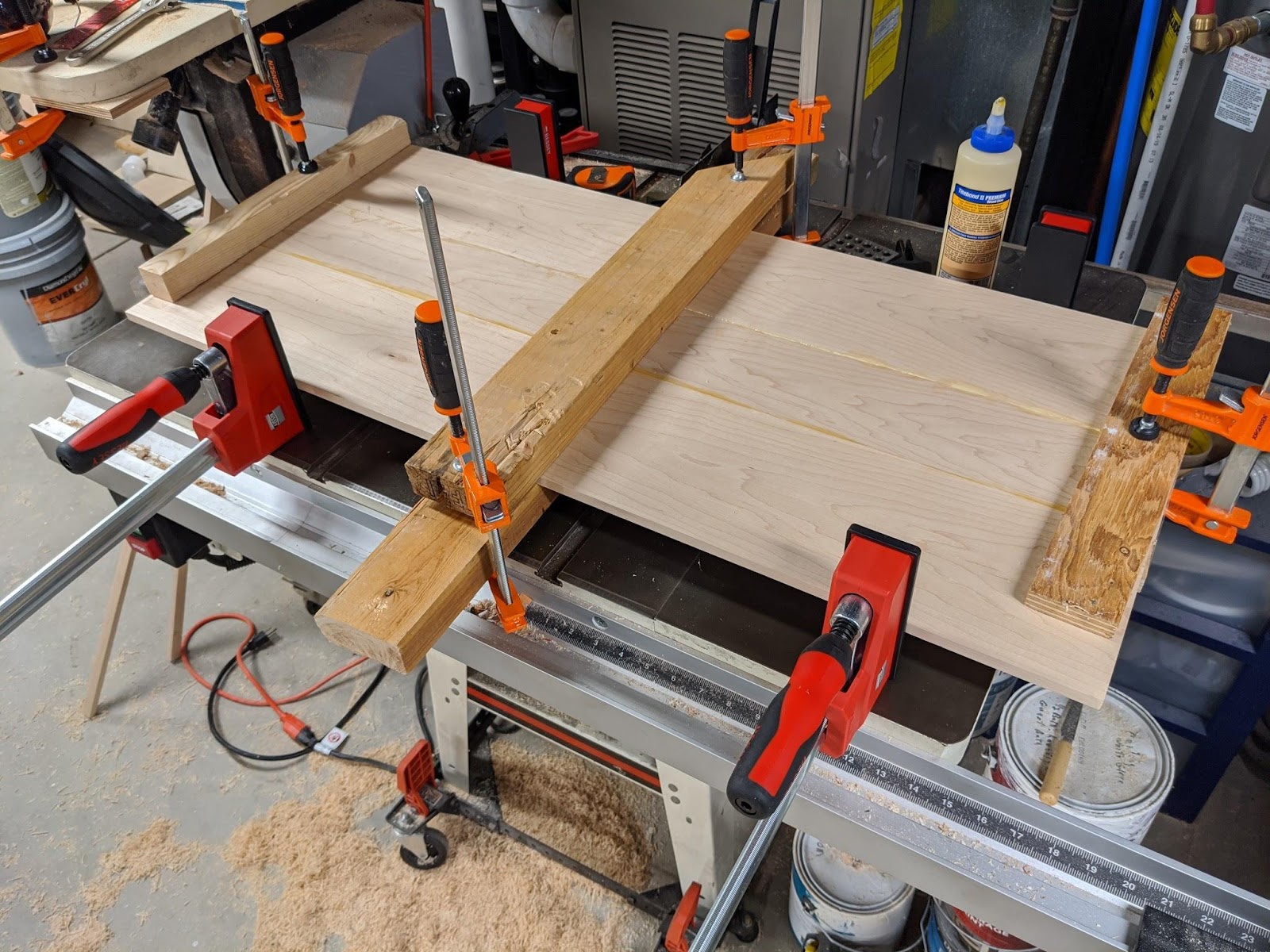
I could then use my CNC to flatten and cut out the profile.
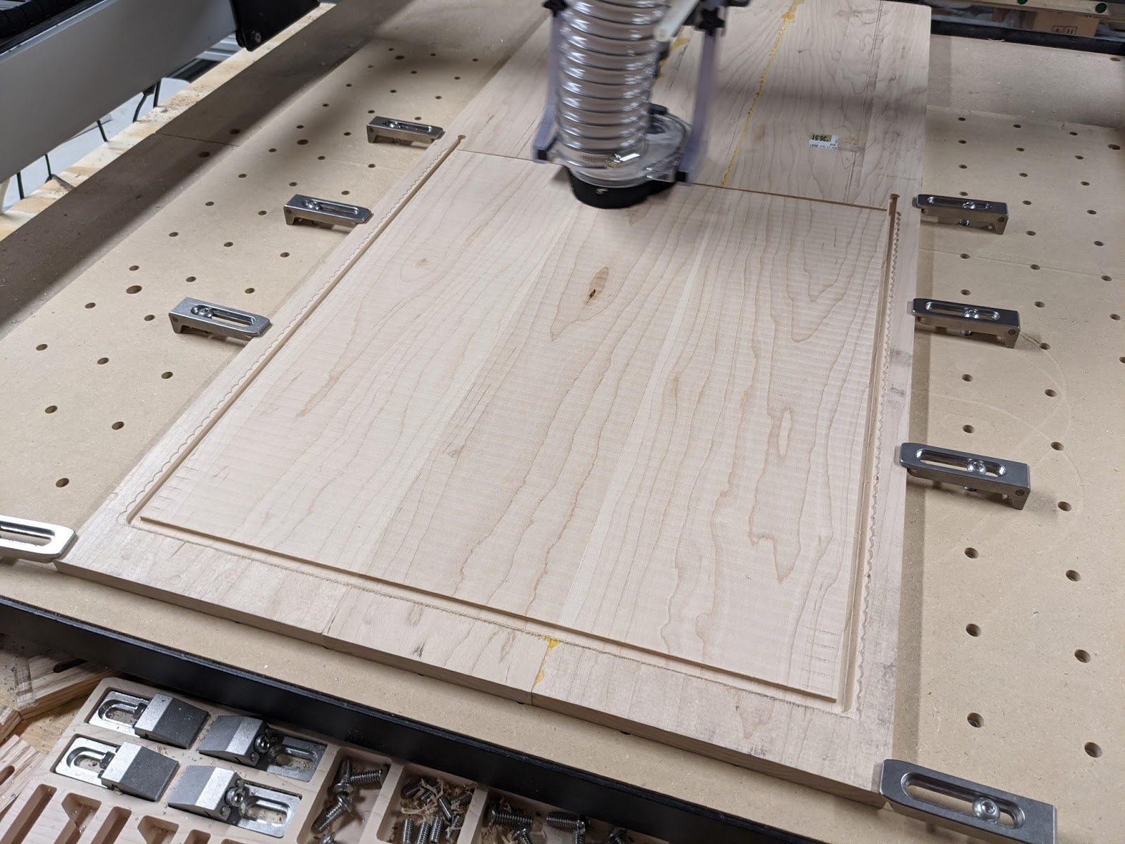
The clock is too big for my Shapeoko XXL so I had to do all the operations in two halves. Once I had the first side done, I could flip it over and flatten out the other side to get the entire face perfectly flat.
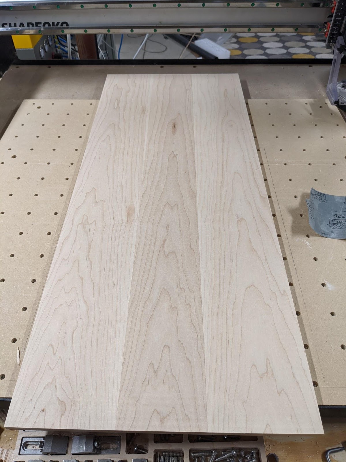
The board was then ready to mill out the pockets for the clocks.
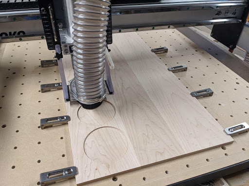
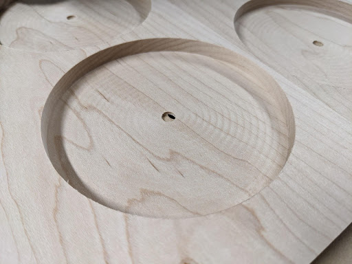
When I made the face plate, it turned out a little thinner than I was originally planning after facing it. That led me to make the bottom of the pockets only 1.5mm thick. This still turned out to be plenty strong.
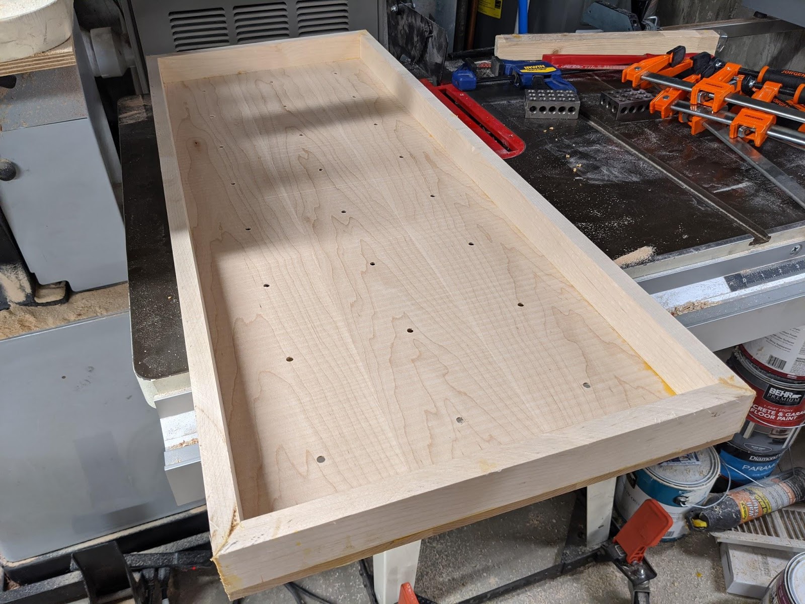
I then built up a frame and glued it together.

Next, I had to make the hands. I chose to use padauk which is a nice red wood that turns to a deep reddish brown over time. I used this wood for drawer pulls in my kitchen where the clock would be hung and I thought it would look good if they matched.
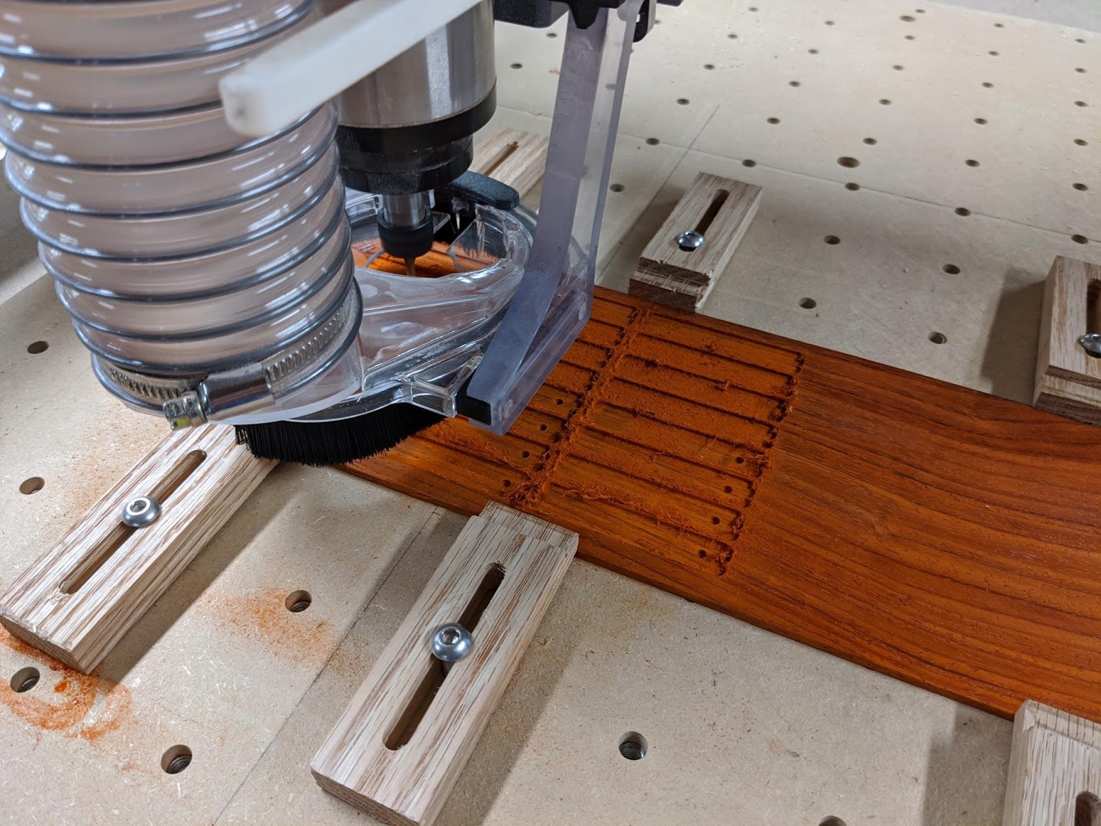
The hands were machined out of ⅛” stock that I milled down to 2mm thick.
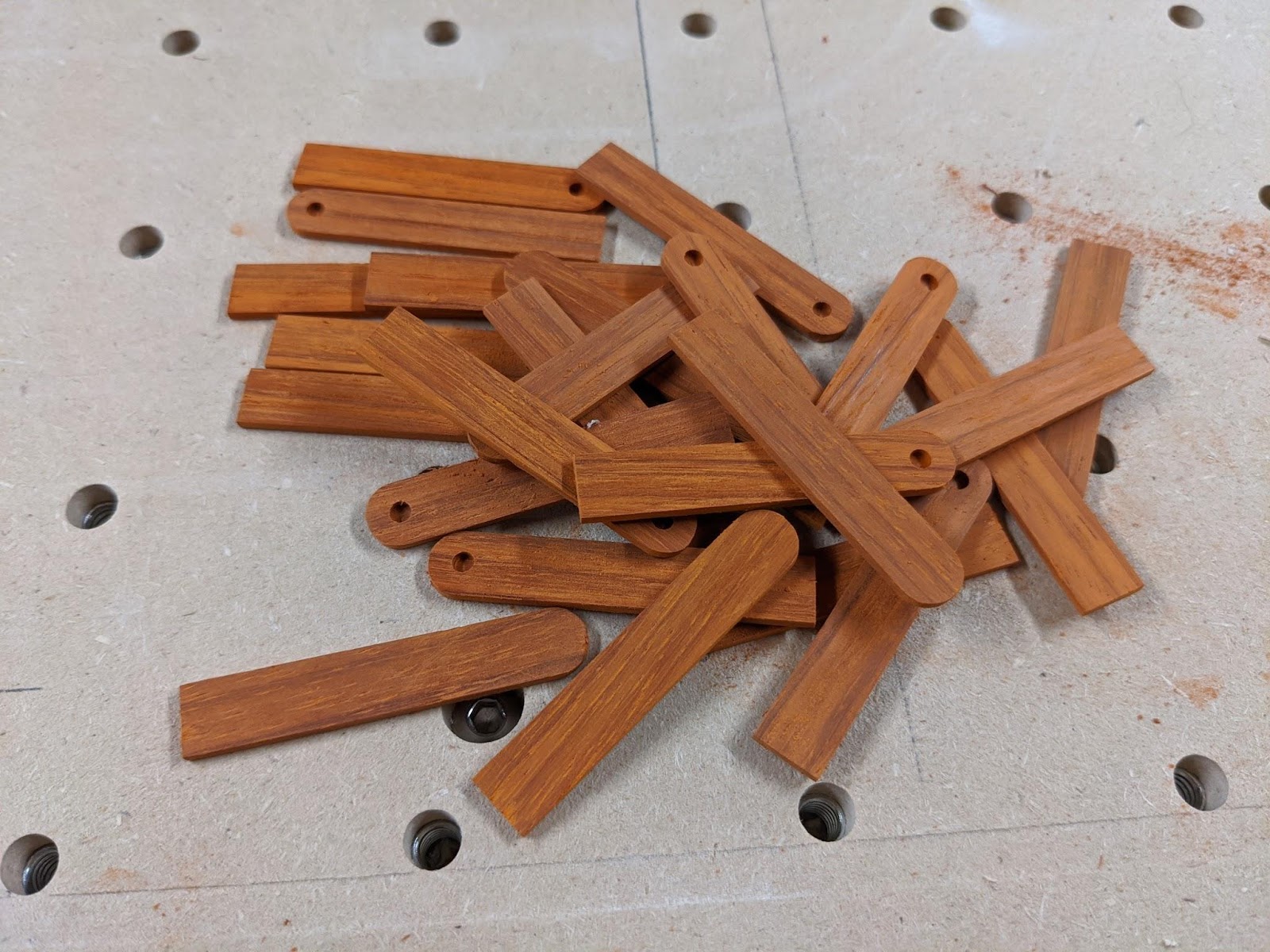
With the hands done, I glued all the movement assemblies to the clock.
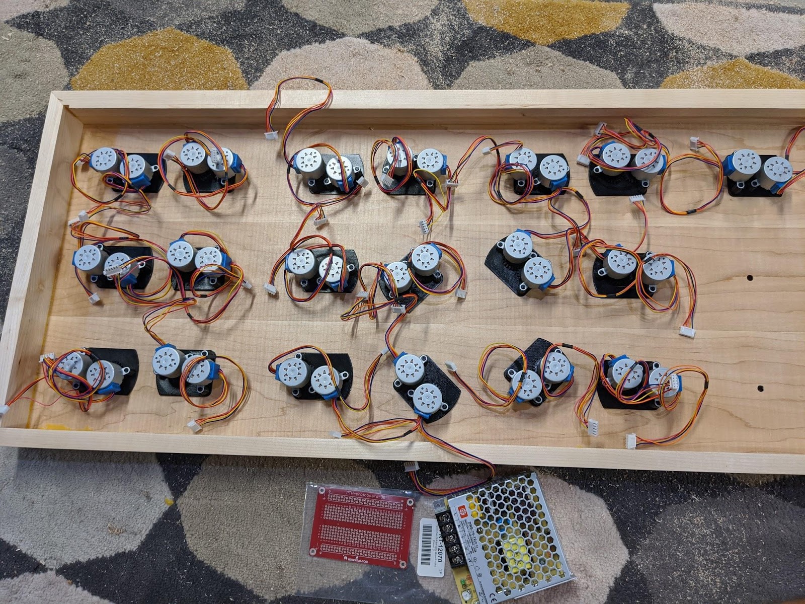
Four of them are rotated at weird angles to make room for the power supply. This is a 12V 6A supply that is plenty for all the motors.
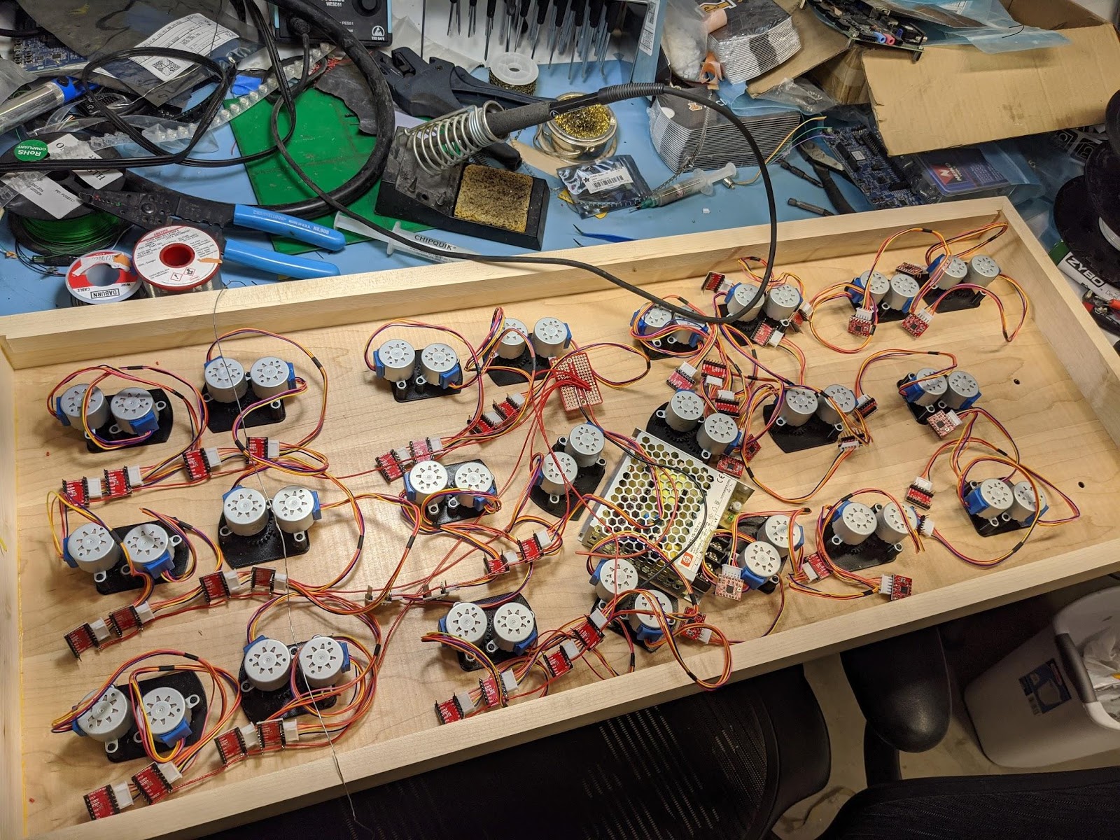
I used generic A4988 stepper drivers to control the motors. I was able to bend the motor pins and plug the motors directly into them after swapping two of the wires on the motor's connector.


With all these attached, I could start wiring them all up to power.
This picture is missing two movements because I was short 4 motors at the time.
Each driver needed to be wired up to the 12V supply for the motors and 3.3V for the control logic.
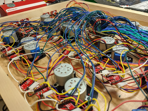
Each group of 6 that makes up a digit also had their enable pins wired together and routed to the Alchitry Au. Every driver had a direction and step signal that had to be wired back to the Au as well. As you can tell from the picture, the wiring quickly became a huge tangle.
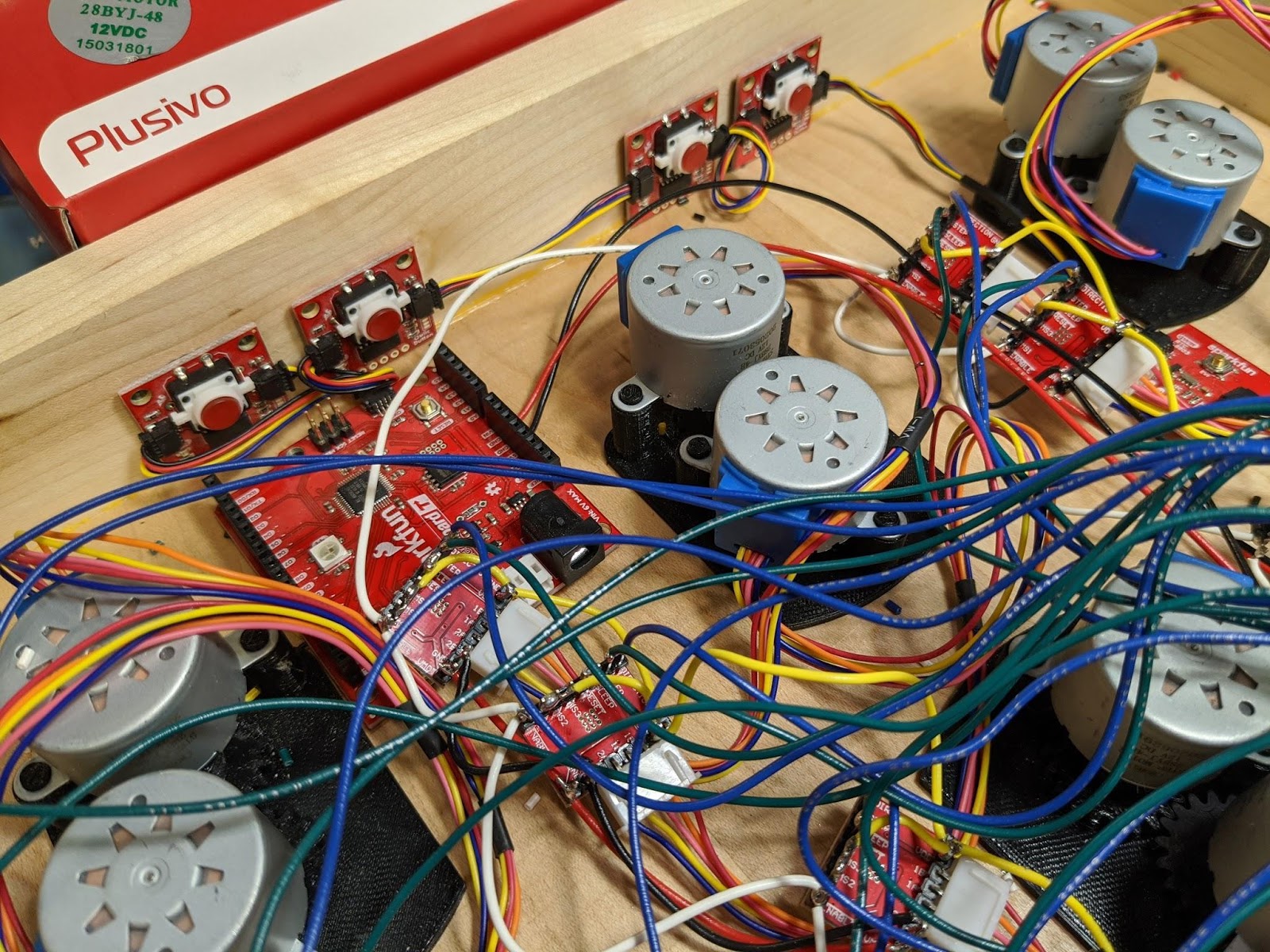
I needed a way to set the time so I added four Qwiic buttons. Since I was already doing enough wiring, using the Qwiic connectors made it a LOT easier. The top pair is hour up/down and the bottom pair is minute up/down.
After the buttons, there is a RV-8803 real-time clock also connected to the Qwiic bus. The RTC being battery backed meant that I wouldn’t need to set the time every time I reprogrammed or unplugged the board.
Finally, the Alchitry Au is connected. It has to be at the end of the chain since it only has one Qwiic connector on it. I also removed the power wire from the Qwiic cable so the 3.3V regulator on the Alchitry Au wouldn’t conflict with the 3.3V regulator on the RedBoard Turbo.
The microcontroller is the RedBoard Turbo. I used this simply because it had a Qwiic connector and I had it on hand. Really, any microcontroller with a Qwiic connector could be used. The computational power needed is minimal.
The Alchitry Au and the RedBoard Turbo both require 5V. I used a small regulator intended for RC vehicles that would regulate the 12V down to 5V at up to 2A.
I wired up the stepper drivers to use half stepping. Initially I set it up to use 1/16 micro stepping but the motors made an audible whine when not on a half or full step. I also really didn’t need the resolution.
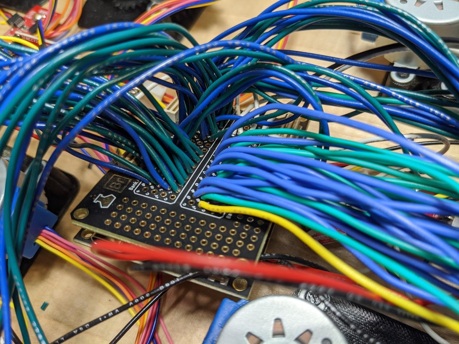
The 102 wires going into the FPGA don’t really matter what pins they connect to. It is only important you keep track of which ones you choose. The actual pinout is defined in the constraint file of the FPGA design.
With all the wiring done, I could clean up the wiring a bit and put the hands on the clock.


That’s basically it for the physical build. The wiring wasn’t complicated, just very tedious.