TFMini - Micro LiDAR Module Hookup Guide
Contributors:
 bboyho
bboyho 
Hardware Hookup
Advanced Users: For those that have experience with Arduino, you could go smaller and use a 5V/16MHz Arduino Pro Mini! Just make sure to also power the TFMini with 5V and use a logic level converter.
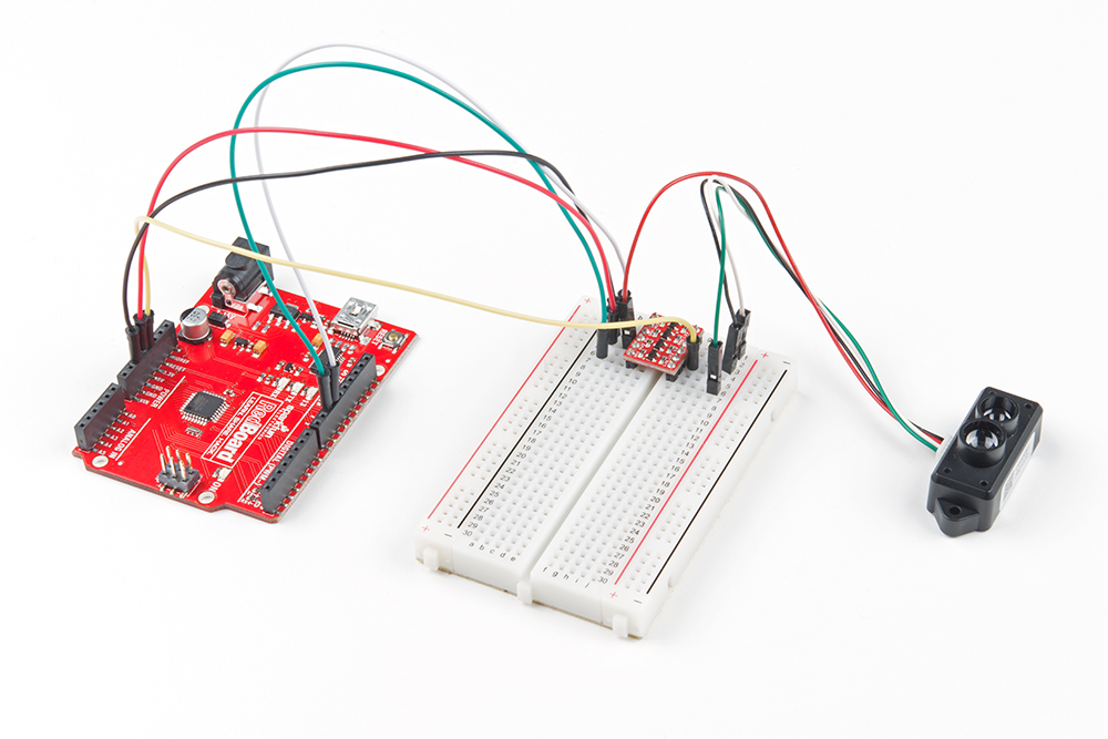
For the purpose of this tutorial, we will be using a 5V Arduino. A microcontroller and logic level converter is required in order to read the sensor values through the serial UART pins. Make sure to solder the male header pins to the converter before making the connections on a breadboard. Begin by making a connection from an Arduino's high side and following the connection to the TFMini. Then continue to make the rest of the connections by following the hookup table listed below.
| 5V Arduino w/ Atmega328P | Logic Level Converter (High Side) | Logic Level Converter (Low Side) | TFMini |
|---|---|---|---|
| Software Serial RX (Pin 10) |
HV1 | LV1 | UART_TX (3.3V TTL) (Pin 1) |
| Software Serial TX (Pin 11) |
HV4 | LV4 | UART_RX (3.3V TTL) (Pin 2) |
| 3.3V | LV | ||
| 5V | HV | Vin (4.5V-6V) (Pin 3) |
|
| GND | GND | GND | GND (Pin 4) |
Once we are finished, it should look like the image below.