TFMini - Micro LiDAR Module Hookup Guide
Introduction
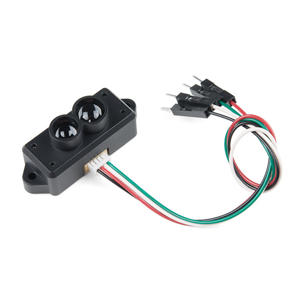
The TFMini is a ToF (Time of Flight) LiDAR sensor capable of measuring the distance to an object as close as 30 cm and as far as 12 meters! The TFMini allows you to integrate LiDAR into applications traditionally reserved for smaller sensors such as the SHARP GP-series infrared rangefinders. In this tutorial, you will learn how to connect to the TFMini using an Arduino microcontroller.
TFMini - Micro LiDAR Module
SEN-14588Required Materials
To follow along with this tutorial, you will need the following materials. You may not need everything though depending on what you have. Add it to your cart, read through the guide, and adjust the cart as necessary.
Tools
You will need a soldering iron, solder, and general soldering accessories.
Weller WLC100 Soldering Station
TOL-14228Suggested Reading
If you aren't familiar with the following concepts, we recommend checking out these tutorials before continuing.
Serial Communication
Installing an Arduino Library
Logic Levels
Hardware Overview
The sensor works by sending a modulated near-infrared light out. The light that is reflected from the object returns to the sensor's receiver. The distance between the two can be converted using the sensor by calculating the time and phase difference. The distance measured may vary depending on the environment and the reflectivity of object.
Input Power
According to the datasheet (pg 4) the input voltage is between 4.5V-6V. In this tutorial, we will be applying 5V to the sensor.
You may want to consider providing a sufficient power supply when using the sensor in a project.
Logic Levels
While the sensor can be powered at 5V, the serial UART pins are only 3.3V logic. Make sure to use a logic level converter when reading the sensor with a 5V microcontroller.
Pinout
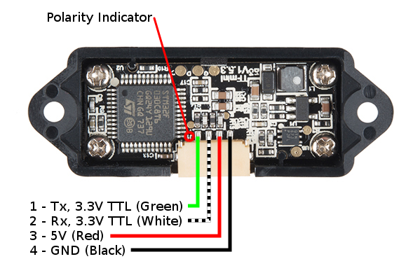
There is a marking next to the polarized connector to indicate the polarity as "J1" as indicated in the image below. This is useful when referencing sensor's pinout.
| Pin Number | TFMini Pinout | Wire Color |
|---|---|---|
| 1 | UART_TX (3.3V TTL) | Green |
| 2 | UART_RX (3.3V TTL) | White |
| 3 | 5V | Red |
| 4 | GND | Black |
Hardware Hookup
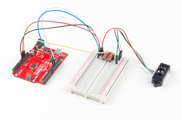
For the purpose of this tutorial, we will be using a 5V Arduino. A microcontroller and logic level converter is required in order to read the sensor values through the serial UART pins. Make sure to solder the male header pins to the converter before making the connections on a breadboard. Begin by making a connection from an Arduino's high side and following the connection to the TFMini. Then continue to make the rest of the connections by following the hookup table listed below.
| 5V Arduino w/ Atmega328P | Logic Level Converter (High Side) | Logic Level Converter (Low Side) | TFMini |
|---|---|---|---|
| Software Serial RX (Pin 10) |
HV1 | LV1 | UART_TX (3.3V TTL) (Pin 1) |
| Software Serial TX (Pin 11) |
HV4 | LV4 | UART_RX (3.3V TTL) (Pin 2) |
| 3.3V | LV | ||
| 5V | HV | Vin (4.5V-6V) (Pin 3) |
|
| GND | GND | GND | GND (Pin 4) |
Once we are finished, it should look like the image below.
Example Code
Note: This example assumes you are using the latest version of the Arduino IDE on your desktop. If this is your first time using Arduino, please review our tutorial on installing the Arduino IDE. If you have not previously installed an Arduino library, please check out our installation guide.
Download and install Peter Jansen's Arduino TFMini library using the library manager. You can also manually install it from the GitHub Repository by downloading the library from the button below.
Grab a mini-USB cable and connect the Arduino to your computer. Upload the BasicReading.ino that was included in the library's examples to your Arduino. Make sure to use the correct COM port and board selection.
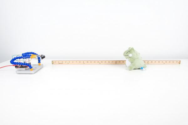
Once uploaded, try moving an object in front of the sensor to test. In the example below, a third hand was used to hold the TFMini when detecting an object at a certain distance away from the sensor. Since the sensor is not able to detect an object when less than 11.8 inches (or 30cm = 0.3m) away, the object under test was placed at 20 inches and 30 inches.
 |
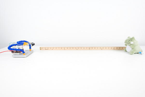 |
| TFMini Reading an Object at 20 Inches | TFMini Reading an Object at 30 Inches |
Opening the serial monitor at 115200, you may see an output similar to the values printed below. Using a yard stick, the values responded as expected when moving an object between 20 inches and 30 inches.
Initializing...
54 cm      sigstr: 457
54 cm      sigstr: 456
54 cm      sigstr: 456
54 cm      sigstr: 456
55 cm      sigstr: 456
54 cm      sigstr: 456
54 cm      sigstr: 456
54 cm      sigstr: 457
67 cm      sigstr: 340
70 cm      sigstr: 315
71 cm      sigstr: 315
77 cm      sigstr: 283
77 cm      sigstr: 283
77 cm      sigstr: 283
77 cm      sigstr: 283
77 cm      sigstr: 284
78 cm      sigstr: 281
78 cm      sigstr: 281
78 cm      sigstr: 282
78 cm      sigstr: 282
78 cm      sigstr: 283
TF Mini error: too many measurement attempts
Last error:
ERROR_SERIAL_NOHEADER
65535 cm      sigstr: 65535
This may be caused by your Arduino not properly communicating with the TFMini. For example, the maximum baud an Arduino at 8MHz can handle with the software serial library is 57600 baud. If you are using a 3.3V/8MHz Arduino Pro Mini with a baud rate of 115200, it is probably too high which can cause unreliable readings. It is recommended to use a 5V/16MHz Arduino if you are using the software serial library to communicate with the sensor at 115200. As an alternative to check if the TFMini is still functioning at small distances, you can try using the TFMini's GUI with a USB-to-Serial cable. Just make sure that you are providing 5V for Vcc and communicating with 3.3V logic levels.
Resources and Going Further
Now that you've successfully got your TFMini up and running, it's time to incorporate it into your own project! For more on the TFMini, check out the links below:
- Datasheet (PDF)
- BeneWake
- Additional Examples
- Instructables: Benewake Lidar TFMini (Complete Guide) - For additional examples with a USB-to-Serial converter and Python, check out this guide! It's possible to use the TFMini with a Raspberry Pi!
- DIY Drones Forum: How to Install Benewake TFSeries on PixHawk - Check out this forum post to connect the TFMini to a PixHawk in order to detect the absolute altitude of your drone.
- GitHub Repo: TFMINI_MAXBOTIX_EMULATOR
- GitHub Repo Arduino Library
Need some inspiration for your next project? Check out some of these related tutorials:
