TEMT6000 Ambient Light Sensor Hookup Guide
 Michael Bartlett
Hardware Overview
As you can see from the image below, the TEMT6000 is about as simple as it gets when it comes to breakout boards. The three pins broken out are labeled on the top of the board.
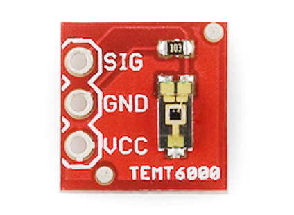
The function of each pin can be found in the table below.
| Symbol | Description |
|---|---|
| SIG | Output Voltage from the divider circuit |
| GND | GND (0V) |
| VCC | Collector Voltage (should not exceed 6V) |
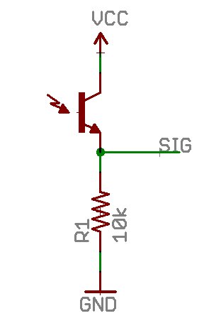
Being a phototransistor, this sensor acts just like any other NPN transistor -- the greater the incoming light on the Base, the the more current that can flow from the Collector to the Emitter. Only light that falls within the visible spectrum (390–700 nm) will alter the Base. Infrared, ultraviolet, or any other light we can’t directly see will have no effect on the sensor.
This sensor can handle voltages from both 5V and 3.3V devices.
To make taking light measurements as easy as possible, this sensor has been designed into a voltage divider circuit. The TEMT600 acts as one of the resistors in the divider, and, as the light hitting it changes, so too does the voltage on the SIG pin. To read that voltage, simply connect the SIG pin on the TEMT6000 to any analog to digital conversion pin on your microcontroller.
The voltage value returned from the SIG pin will vary depending on what voltage is being used to power the sensor and depending on the resolution of your ADC.