TEMT6000 Ambient Light Sensor Hookup Guide
 Michael Bartlett
Example Project: Night Light
Required Materials
We'll be reusing a lot of parts from before. In fact, the only difference is we're upping the ante and using an RGB LED instead of a single color LED! Nevertheless, here's a list of everything you'll need:
Hookup
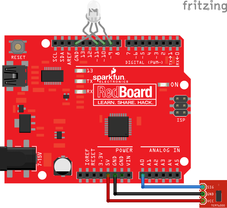
Since we're reusing a lot of the same parts, they're mostly going to occupy the same pins on the RedBoard: VCC on the breakout should connect to 5V on the RedBoard, GND to GND, and SIG to A0.
| TEMT6000 Pin | Arduino Pin |
|---|---|
| SIG | A0 |
| GND | GND |
| VCC | 5V |
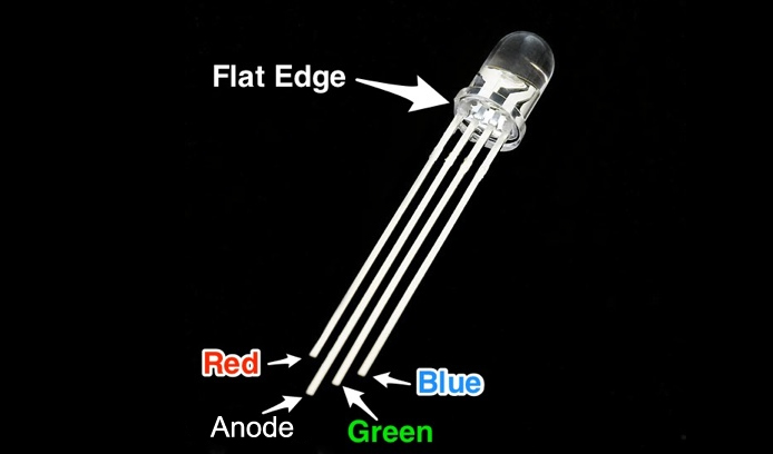
The main difference is now we have an RGB LED that has twice as many legs, but the idea is still the same. The longest leg on a common anode RGB LED is going to be the pin that goes to the GND pin. Most Arduino boards have a group of three consecutive PWM pins, and these happen to be pretty close to a GND. If the legs on your LED aren't bent too bad, you should be able to see which is the second longest leg—that's the cathode for the red LED, and that should go to pin 9. Plug the remaining two legs into pins 10 and 11 in the orientation they appear to go in easiest. Use the image below, if you can't tell the difference between the legs.
This table should clarify, which pins are connected.
| RGB LED Pin | Arduino Pin |
|---|---|
| Red Cathode | Pin D9 |
| Common Anode | GND |
| Green Cathode | Pin D10 |
| Blue Cathode | Pin D11 |
Here's what the setup should look like once everything is plugged in:
Programming
The code for this one is going to look a little different. The challenge is that we want to cycle through all the colors without being stuck in a loop and unable to read light values until the loop is done. The way around this is to use a function that will take a variable that counts and returns a color based on how far that variable has counted. This way, for every "count" (cycle of the loop) we have time to stop and check our TEMT6000 for a reading. There are some other little tricks that are explained in the comments.
The drill for uploading the code is the same as before.
language:c
#define LS_PIN A0  //Light Sensor pin
#define R_PIN  9   //Red pin
#define G_PIN  10  //Green pin
#define B_PIN  11  //Blue pin
#define POWER  4   /* Power to raise the ratio of read-value to largest read-value.
                    * Higher is less likely to be on during the day,
                    * but too high and it may not turn on once it's night.*/

#define TIME  500 /* The amount of milliseconds before taking a step through the color function.
                   * Higher values = slower transitions between colors.*/

uint16_t  _max =  0;  //Holds the largest brightness reading so far.
byte      count = 0;  //Keeps track of where we are on the color spectrum
float     ratio = 0;  //Stores the ratio of current brightness to largest recorded brightness.

void setup() {
  pinMode(LS_PIN,  INPUT);  //Reading in
  pinMode(R_PIN,  OUTPUT);  //Writing out*
  pinMode(G_PIN,  OUTPUT);  //*
  pinMode(B_PIN,  OUTPUT);  //*
  Serial.begin(9600);
}

void loop() {
  float reading = analogRead(LS_PIN); //Take brightness reading
  if (reading > _max) _max = reading; //See if it's the brightest so far

  /* Calculate the ratio between the reading and the max, raise the power, and average it with
   * the last reading to get our ratio but minimize flickering. */
  ratio = (ratio + pow(1.0 - reading / float(_max), POWER)) / 2.0;
  /* We're subtracting the ratio from 1 because we want brighter readings to result
   * in a dimmer display of colors, and smaller readings to result in brighter displays. */

  //Write the color from our spot in the spectrum at the relative brightness to the LED
  analogWrite(R_PIN, Rainbow(count + 170) * ratio);
  analogWrite(G_PIN, Rainbow(count + 85)  * ratio);
  analogWrite(B_PIN, Rainbow(count)       * ratio);
  /* Each color has the same pattern of increasing and decreasing brightness, just not synchronously.
   * We can reuse the same function and carefully offset each color to make sure we get to see all
   * the colors.*/


  if (!(millis() % TIME)) count++;
  /* There's a lot going on in this concise use of syntax. Essentially, whenever millis() (the
   * amount of milliseconds since the arduino has been on) is evenly divisble by TIME (i.e.
   * TIME milliseconds have passed) then the modulo operator (%) will return 0, which evaluates
   * as FALSE. The ! in front of the expression means invert, so this means every TIME milliseconds,
   * the expression will return TRUE. If it's TRUE, we take a step through the color spectrum. Bytes
   * can only count to 255 before they reset back to 0. The overflow of "count" is a passive way to
   * take us back to the start of the color spectrum without having to explicitly set "count" to 0.*/
}

/* Returns an appropriate value in 0-255 for a given value in 0-255. With good timing, it can be used
 * to cycle through the entire color spectrum. */
byte Rainbow(byte i) {
  if (i > 213) return i * 6;
  if (i > 127) return 0;
  if (i > 85)  return 255 - i * 6;
  return 255;
}
Once the code is uploaded, you should have yourself an automatic mood night light! Here's ours in action: