TEMT6000 Ambient Light Sensor Hookup Guide
 Michael Bartlett
Hardware Assembly
First, let's fire up our light sensor and start collecting readings from it.
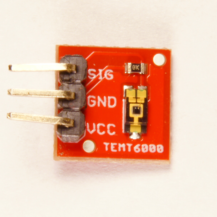
We recommend soldering male header-pins to the breakout to make it simpler to prototype with:
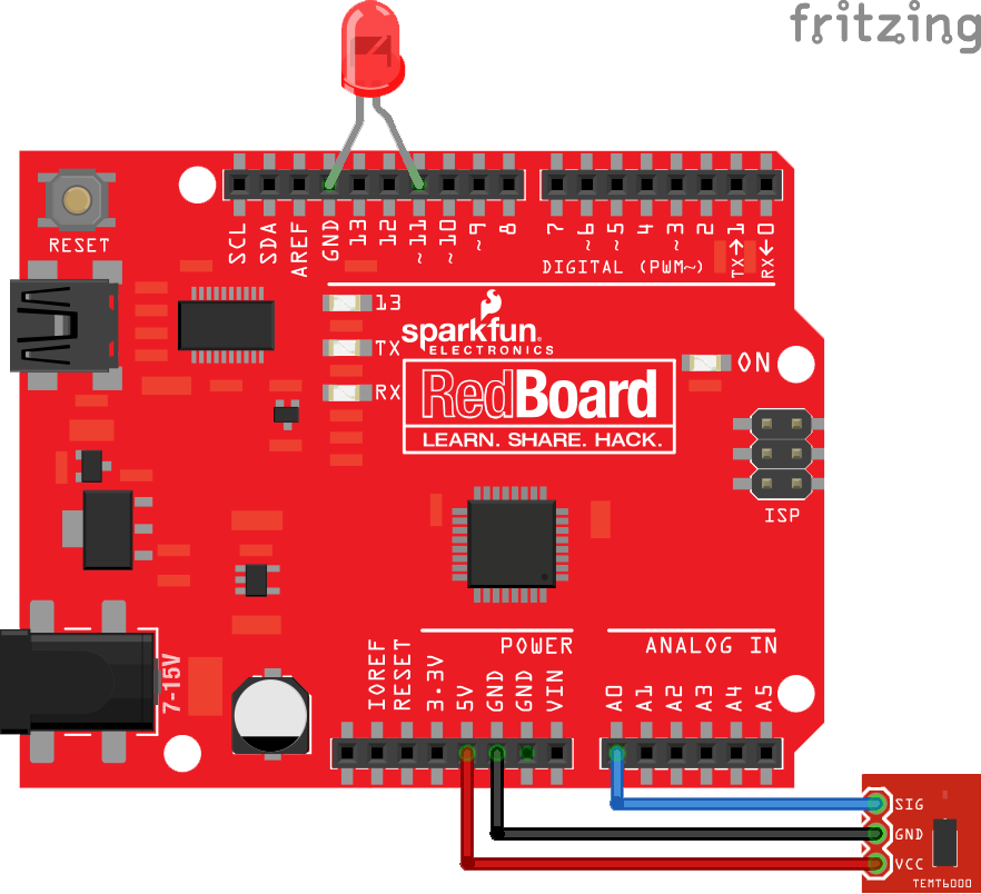
The rest is just plugging parts into the RedBoard. Start by taking any basic LED of your preferred color and placing its anode leg (the long leg) into a pin whose label is followed by a ~. This mark on the RedBoard means the pin supports pulse-width modulation (PWM), which is just a technical way of saying we can control the voltage output of the pin digitally; in this case it lets us control the apparent brightness of our LED. We want this because our LED is going to show us the relative brightness of the world through the eyes of our TEMT6000. If you're using a different board, be sure to read its documentation closely to see which of its pins support PWM. Place the other leg into ground (GND).
We used pin 11 on the RedBoard because it is the PWM pin closest to a ground pin. Thus, we didn't have to deform our LED's legs too much. This is the pin we'll be using in the sample code, so be sure to modify that constant if you're using a different physical pin.
Next comes the light sensor breakout. Start by connecting the female ends of some male-to-female jumper cables to the pins we soldered to it earlier. Connect VCC on the sensor to the 5V pin on the RedBoard, GND to GND, and SIG to any analog pin (we'll be using A0 in the sample code). Use the table below to aid in wiring.
| TEMT6000 Pin | Arduino Pin |
|---|---|
| SIG | A0 |
| GND | GND |
| VCC | 5V |
Here's a diagram of how the circuit should look: