Teensy XBee Adapter Hookup Guide
 MTaylor
Software
Note: This example assumes you are using the latest version of the Arduino IDE on your desktop. If this is your first time using Arduino, please review our tutorial on installing the Arduino IDE. If you have not previously installed an Arduino library, please check out our installation guide.
Working with Your Serial UART Ports
Working with wireless devices is more difficult than just a single Arduino because more than one serial port is in use. Where Arduino allows you to simply load the serial monitor to talk to your code, be extra careful remembering which ports what device and which terminal are using.
The first serial link in use is between the XBee and computer through the serial explorer. Get this port open and communicating to the XBee, then leave it alone. It ushers bytes you type into it into the air, and prints whatever comes into it's antenna to your screen. When the system is fully functional, this terminal will tell you what buttons are being pressed.
The second serial link is the Arduino serial monitor, which connects to the Teensy over the USB cable. Eventually the Teensy will be disconnected from the computer but it can be useful to get debugging information from your program while working with it. Be careful not to confuse it with the other serial ports. When you upload a sketch, the serial monitor automatically closes. If you're using a 3rd party terminal here make sure it is closed before upload in order to free up the USB port for programming.
The trickiest serial link in this project is the one that goes from the Teensy to the XBee because we have little information about it. Without expensive scopes, use the Din and Dout LEDs to monitor if there is activity from the Teensy to the XBee. One illuminates when the Teensy sends data to the XBee, and the other for showing when data is coming from the XBee to the Teensy.
Serial1.print() with a BYTE to pass serial data. You may receive the following error when compiling code:
teensy_3_1_xbee_UART1_example:31: error: 'BYTE' was not declared in this scope
     Serial1.print(Serial.read(), BYTE);

                                  ^

teensy_3_1_xbee_UART1_example:37: error: 'BYTE' was not declared in this scope
     Serial.print(Serial1.read(), BYTE);

                                  ^

'BYTE' was not declared in this scopeBYTE is no longer a keyword. Instead of:
Serial1.print(Serial.read(), BYTE); print methods with write. Then remove any instance of ", BYTE". The code in this tutorial has been updated to reflect this note.
Serial1.write(Serial.read()); Test Your Serial and XBee Configuration
Two sketches are provided to ease bringing the XBees on line. They pass data between the XBee and the serial monitor using the HW UART or the SW UART 'AltSoftSerial' library. You can get them from the GitHub repository for the Teensy 3.1 XBee Adapter or by copy-pasting the code.
Hardware UART Example teensy_3_1_xbee_UART1_example.ino
The following uses the Teensy's hardware serial UART to create a serial passthrough in the teensy_3_1_xbee_UART1_example.ino sketch in order to test the hardware UART and XBee configurations. Make sure to set the adapter's serial switch to UART1. Then load and run the example.
language:c
//Serial test using the hardware uart on pins 0/1 (UART1).
//Connect an XBee and Teensy 3.1 to the adapter board
//Connect an XBee to a serial terminal of your choice (USB dongle for example)
//
//Characters sent out the XBee terminal go:
// Onto the airwaves -> into UART1 RX -> out the serial monitor
//
//Characters sent out the serial monitor go:
// Out the UART1 TX pin -> onto the airwaves -> out the SBee serial terminal
//
//Be sure to select UART1 on the adapter board's switch for HW serial

void setup()
{
  //Begin serial monitor port
  Serial.begin(9600);
  //Begin HW serial
  Serial1.begin(9600);

}

void loop()
{
  // Take data received from the serial monitor and pass it to the HW UART
  if(Serial.available())
  {
    Serial1.write(Serial.read());
  }

  // Take data received from the HW UART and pass it to the serial monitor
  if(Serial1.available())
  {
    Serial.write(Serial1.read());
  }

  //Wait to reduce serial load
  delay(5);
}
Open the serial monitor. Text entered in the serial monitor will be passed to the XBee, and come out the X-CTU (or other, I use Tera Term) serial monitor. Typing in that terminal will send the text back to the Arduino serial monitor.
Software Serial UART Example teensy_3_1_xbee_SUART_example.ino
The following uses the Teensy's software serial UART to create a serial passthrough in the teensy_3_1_xbee_SUART_example.ino sketch in order to test the hardware UART and XBee configurations. This sketch works much like the UART1 example but with the AltSoftSerial library, leaving the hardware UART free to connect to other resources. Make sure to set the adapter's switch to S-UART and run the sketch.
language:c
#include <AltSoftSerial.h>
//Serial test using the software uart on pins 20/21.
//Connect an XBee and Teensy 3.1 to the adapter board
//Connect an XBee to a serial terminal of your choice (USB dongle for example)
//
//Characters sent out the XBee terminal go:
// Onto the airwaves -> into S-UART RX -> out the serial monitor
//
//Characters sent out the serial monitor go:
// Out the S-UART TX pin -> onto the airwaves -> out the SBee serial terminal
//
//Be sure to select S-UART on the adapter board's switch for HW serial

AltSoftSerial altSerial;

void setup() {
  // initialize serial communication at 9600 bits per second:
  //Begin serial monitor port
  Serial.begin(9600);
  //Begin SW UART serial
  altSerial.begin(9600);

}

// the loop routine runs over and over again forever:
void loop() {
  // Take data received from the serial monitor and pass it to the HW UART
  if(Serial.available())
  {
    altSerial.write(Serial.read());
  }

  // Take data received from the HW UART and pass it to the serial monitor
  if(altSerial.available())
  {
    Serial.write(altSerial.read());
  }

  //Wait to reduce serial load
  delay(5);
}
Text should be passed between the two serial terminals.
Running the Demo Sketch
One sketch is provided to demonstrate passing data between a computer with SparkFun XBee Explorer USB and a remote Teensy with XBee. You can get it from the GitHub repository for the Teensy 3.1 XBee Adapter or by copy-pasting the code.
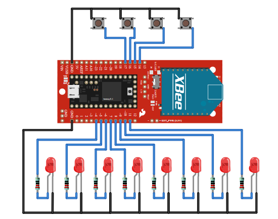
Hardware Hookup
If you have not already, make sure to connect LEDs and buttons to the remote Teensy with XBee.
- Attach buttons to pins 14-17 of the Teensy, and to ground. The pins are pulled up inside the Teensy and will float high until a button is depressed.
- Attach LEDs from pins 4-12 of the Teensy, through a current limiting resistor, to ground. It's not so important to have all 8, 2 or 3 is enough to demonstrate the effect.
Remote Control of I/O teensy_3_1_xbee_buttons_and_leds_example.ino
This sketch demonstrates bi-directional communication and shows off operation that is more than just data echo.
language:c
#include <AltSoftSerial.h>
//To use this example you will need to have the following connections:
//  4 buttons connected to pins 14 through 17, normally open, short to ground.
//  8 LEDs connected to pins 4 through 11, each with their own current limiting resistor.
//  The sketch is intended to have leds with a common ground, though using a common power
//  will work invertedly.
//
//You will also need:
//  A Teensy 3.1 to XBee adapter board with XBee
//  A 2nd XBee connected to serial terminal (USB dongle with Tera Term for example)
//  The S-UART / UART1 switch set to S-UART for a software UART using the altSoftSerial library
//
//Load the sketch and press the buttons.  In the serial terminal the '0's change to '1's.
//Press 1-8 on the keyboard in the terminal window.  The LEDs will illuminate.  Press enter or
//any other key to clear the LEDs.


// Define pin locations
int upleftButton = 14;
int uprightButton = 15;
int downleftButton = 16;
int downrightButton = 17;
int led1Pin = 4;
int led2Pin = 5;
int led3Pin = 6;
int led4Pin = 7;
int led5Pin = 8;
int led6Pin = 9;
int led7Pin = 10;
int led8Pin = 11;

AltSoftSerial altSerial;


void setup() {
  // initialize serial communication at 9600 bits per second:
  Serial.begin(9600);
  altSerial.begin(9600);

  // Setup the pin directions
  pinMode(upleftButton, INPUT_PULLUP);
  pinMode(uprightButton, INPUT_PULLUP);
  pinMode(downleftButton, INPUT_PULLUP);
  pinMode(downrightButton, INPUT_PULLUP);
  pinMode(led1Pin, OUTPUT);
  pinMode(led2Pin, OUTPUT);
  pinMode(led3Pin, OUTPUT);
  pinMode(led4Pin, OUTPUT);
  pinMode(led5Pin, OUTPUT);
  pinMode(led6Pin, OUTPUT);
  pinMode(led7Pin, OUTPUT);
  pinMode(led8Pin, OUTPUT);

}

// the loop routine runs over and over again forever:
void loop() {
  //*******************************************************************//
  // Transmitting.  This section reads button states and builds a packet
  // that is shipped over the airwaves.  The basic packet has a start
  // char of ~, 9 user bytes, and terminates with a carriage return
  // "~000000000\r"

  int buttonState;

  //Write the tilde to the XBee.  This signifies start of packet
  altSerial.write('~');

  // read the input pin:
  buttonState = digitalRead(upleftButton);
  Serial.print("up left is ");
  // print out the state of the button to the serial monitor:
  Serial.println(buttonState);
  buttonState ^= 0x01;
  // write the value to the XBee packet
  altSerial.print(buttonState);

  // read the input pin:
  buttonState = digitalRead(uprightButton);
  // print out the state of the button to the serial monitor:
  Serial.print("up right is ");
  Serial.println(buttonState);
  buttonState ^= 0x01;
  // write the value to the XBee packet
  altSerial.print(buttonState);

  // read the input pin:
  buttonState = digitalRead(downleftButton);
  // print out the state of the button to the serial monitor:
  Serial.print("down left is ");
  Serial.println(buttonState);
  buttonState ^= 0x01;
  // write the value to the XBee packet
  altSerial.print(buttonState);

  // read the input pin:
  buttonState = digitalRead(downrightButton);
  // print out the state of the button to the serial monitor:
  Serial.print("down right is ");
  Serial.println(buttonState);
  buttonState ^= 0x01;
  // write the value to the XBee packet
  altSerial.print(buttonState);

  // fill the rest of the packet with zeros
  altSerial.print('0');
  altSerial.print('0');
  altSerial.print('0');
  altSerial.print('0');
  altSerial.print('0');
  // Proved an end of line char for the interpreter to pick up on
  altSerial.write(0x0D);

  //*******************************************************************//
  // Receiving.  This section check for new serial data and turns on an
  // LED that corresponds to a number key entered.  All other characters
  // including return, LF, CR, etc. cause all LEDs to be turned off.
  if (altSerial.available())
  {
    char c;
    c = altSerial.read();
    switch(c)
    {
    case '1':
      digitalWrite(4, 1);
      break;
    case '2':
      digitalWrite(5, 1);
      break;
    case '3':
      digitalWrite(6, 1);
      break;
    case '4':
      digitalWrite(7, 1);
      break;
    case '5':
      digitalWrite(8, 1);
      break;
    case '6':
      digitalWrite(9, 1);
      break;
    case '7':
      digitalWrite(10, 1);
      break;
    case '8':
      digitalWrite(11, 1);
      break;
    default:
      //Clear all pins on other keys
      digitalWrite(4, 0);
      digitalWrite(5, 0);
      digitalWrite(6, 0);
      digitalWrite(7, 0);
      digitalWrite(8, 0);
      digitalWrite(9, 0);
      digitalWrite(10, 0);
      digitalWrite(11, 0);
      break;

    }

  }


  delay(100);        // delay in between reads for stability
}
Each time the loop() runs, the sketch the Teensy:
- Converts button presses to an ASCII representation
- Prints the button states to the Arduino serial monitor
- Transmits the button states as a series of ASCII characters
- Checks for received data from the XBee. If a number 1-8 is received, the associated LED on pins 14-21 is illuminated. If any other character is received, all 8 LEDs are are switched off.