Teensy XBee Adapter Hookup Guide
Contributors:
 MTaylor
MTaylor 
Hardware Overview
Apart from mechanically connecting the The Teensy and XBee, the adapter has a some features to help you get the most from the hardware. Here's what each section does.
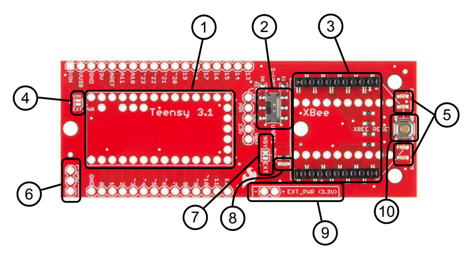
Key Parts of the Adapter
- Teensy 3.2/3.1 (and LC) Footprint - Connect the Teensy here. Make sure to add headers next to the shorter row of pins next to the Teensy's reset button to power the XBee by default.
- UART1/S-UART Switch - Select which serial pins are connected to the XBee (pins 0/1 for the hardware UART, pins 20/21 for the software UART).
- XBee Socket - Plug the XBee in here matching silkscreen shape.
- VIN/EXT Jumper Pad - Short to source Teensy power from the EXT_IN pins.
- XBee Status LEDs - Shows data movement, signal strength, and digital IO pin 5 (XBee signals).
- Spare Ground Connections - My gift to you! More ground pins for reference.
- TNSY/EXT Jumper Pads - Selects the source of power for the XBee. The default is connected to the Teensy's on-board voltage regulator. When providing external power from the EXT_PWR (3.3V) pins, move the solder jumper to the EXT_IN side.
- Power LED - Shows if XBee is getting power.
- EXT_PWR (3.3V) - Supply regulated 3.3v here only when necessary.
- XBee Reset Switch - Resets the XBee.

Bottom View
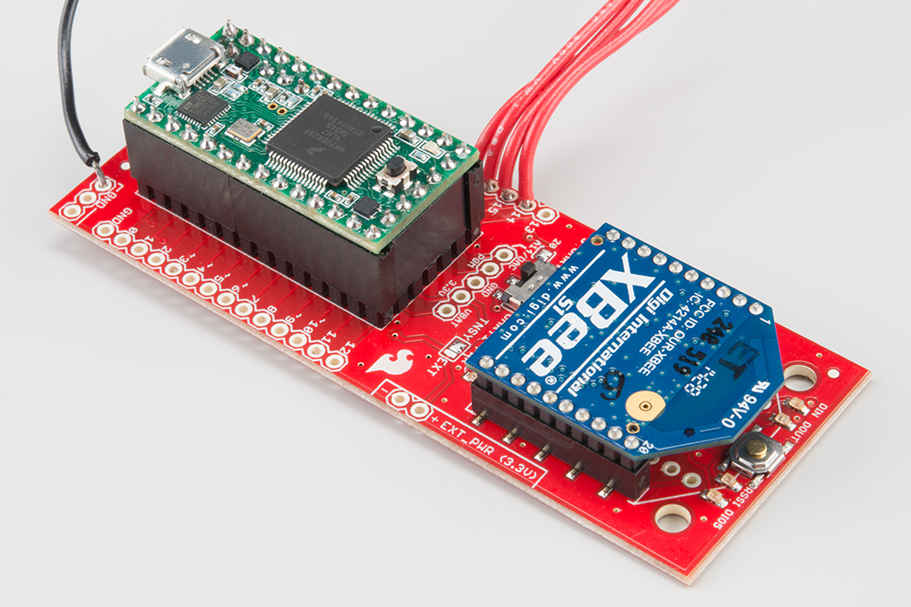
With XBee and Teensy Installed
Don't forget to check out the Getting Started with the Teensy tutorial for information on attaching the Teensy to an adapter.