Stepoko: Powered by grbl Hookup Guide
Hardware: The Stepper Drivers
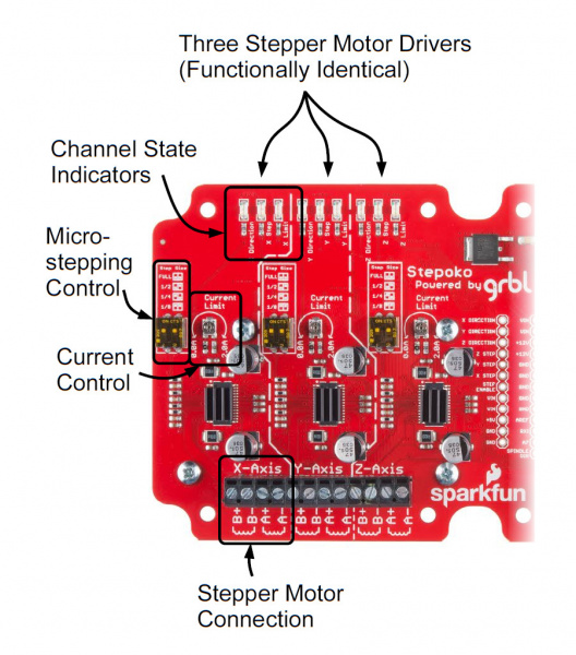
The stepper drivers consist of three identical circuits, one for each axis. Here, one is shown but the application applies to any of them.
Parts of a single axis circuitry:
- State LEDs
- Direction -- Denotes polarity of movement
- Step -- Flashes each time the associated channel steps
- Limit -- Illuminates when a stop switch is active
- Stepper Motor Connection
- Axis driver -- DRV8811
- Microstepping Control Switches
- Heatsinks -- One each on the driver IC and a collective aluminum slug on the backside
- Current control potentiometer
Operation
At the heart of each axis driver is a DRV8811 IC by Texas Instruments. The microcontroller talks to the 8811 by digital control signals (not serial) that: set the direction, enable the motor, and cause a step. Internally, it has a state machine that matches the coil states necessary to get a stepper motor to perform. Modifying the microstepping switches changes that state machine such that the pattern is correct for the microstepping indicated.
The digital portion of the IC operates from 5V by way of the Stepoko's on-board regulator. This is not enough to drive the motors though. The IC has a separate VIN supply that connects directly to the power jack / screw terminals. Whatever the voltage (12V - 30V) supplied, that voltage will be the driving voltage on the motor coils.
All this work is graciously provided by the grbl software that comes pre-installed, so unless you are building new software, how the 8811 works is really not too important. If you are, the DRV8811 datasheet explains in great detail.
