Spectrum Shield Hookup Guide
This Tutorial is Retired!
This tutorial covers concepts or technologies that are no longer current. It's still here for you to read and enjoy, but may not be as useful as our newest tutorials.
View the updated tutorial: Spectrum Shield Hookup Guide (v2)
 Toni_K
 Introduction
Have you ever wanted to have your project react to music? Then this is the product for you! The Spectrum Shield enables your Arduino with the capability of splitting a stereo audio input into 7-bands per channel. You can then read the amplitude of each channel using the ADC on your Arduino allowing you to control everything from LEDs to motors, pumps to relays, or even fire, all with sound.
Materials Required
To follow along with this tutorial, we recommend the following items.
Suggested Reading
We recommend you be familiar with these resources before continuing on with this hookup guide.
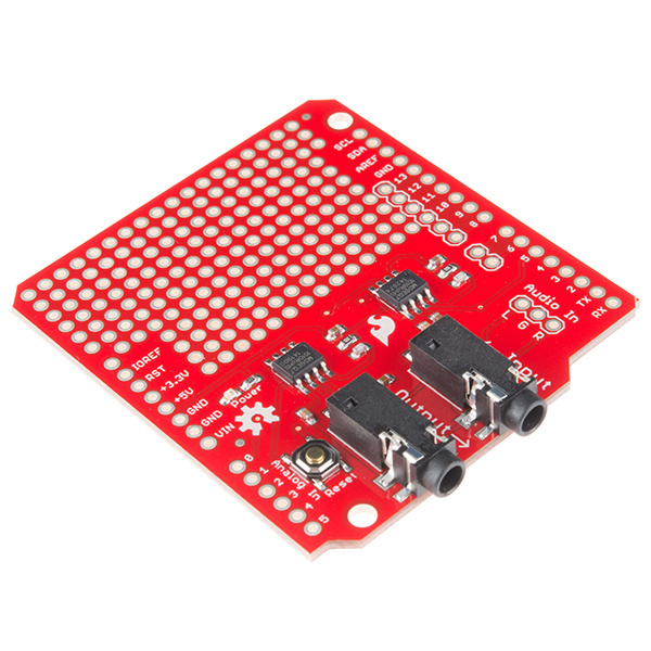
Hardware Overview
Audio Connections
Audio Jacks
The Spectrum Shield contains two audio stereo jacks on board. The first is the audio input jack (labeled "Input"). This allows you to input audio from any device -- such as an MP3 player, or cellular phone -- using a basic audio cable. This connection does not have to be used, as there is another option for adding audio input, at the "Audio In" headers, described below.
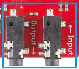
The second audio jack is the audio output, labeled "Output". This jack allows you to route the audio back out to a speaker or other audio system, after the sound levels have been processed by the Spectrum Analyzer ICs.
Audio In Header
For some projects, you may not be piping audio from a pre-processed source such as a cell phone. For users who want to use things like a MEMS Mic Breakout or the Sound Detector as an audio source, there are three header pins that allow you to connect bare wires to your shield.
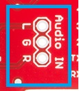
These pins are as follows:
- L = Left Audio Input
- G = Ground Audio Input
- R = Right Audio Input
With both the left and right inputs, you can use stereo devices on these headers.
MSGEQ7 ICs
The real power of this shield comes from the two MSGEQ7 ICs on the board. These are CMOS chips, which are seven band graphic equalizers.
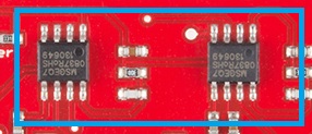
Upon receiving an audio signal in, these ICs split the the spectrum into seven bands, splitting it at the following levels:
- 63Hz
- 160Hz
- 400Hz
- 1kHz
- 2.5kHz
- 6.25kHz
- 16kHZ
For the visual learners, here's the frequency graph from the MSGEQ7 datasheet:
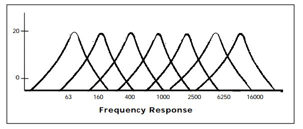
Once the spectrum has been split into these ranges, each band is peak detected and multiplexed. The DC output is a representation of the amplitude of each frequency band. Using the strobe and reset pins on the ICs allows the user to select the DC peak output.
RedBoard Connections
There are 4 main pins that connect the Spectrum Shield with the Arduino/RedBoard or other microcontroller.
Analog Pins - There are two analog pins connected to the MSGEQ7 ICs. Analog 0 is the DC output from the first IC, while Analog 1 is the DC output from the second.
Control Pins - The MSGEQ7 control pins are Strobe and Reset. These are connected to D4 and D5, respectively. In order to enable the Strobe pin, you must pull the Reset pin LOW. To reset the entire multiplexer, pull the Reset pin HIGH.
The Strobe pin, once activated, cycles through each of the channels. After the initial pulse, it starts at 63Hz, pulses each channel until 16kHz, and then repeats, starting back at 63Hz. The DC output for each channel will follow the Strobe pulse.
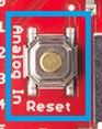
Reset Button
The reset button allows you to reset your Arduino/RedBoard while the shield is inserted. Holding the reset button will pull the reset pin of the ATMega328 low, allowing a system reset. This will restart any sketches currently running on the microcontroller.
Hardware Hookup
Solder Headers
As with any shield, the first step is to choose a connection method. We recommend stackable headers, but you can choose any connection method you prefer. Remeber that his shield uses the Arduino Uno R3 footprint. You will need to solder, so make sure you have all the appropriate supplies before you begin. Please check our tutorial on Arduino Shield Assembly, if you aren't sure how to do this.
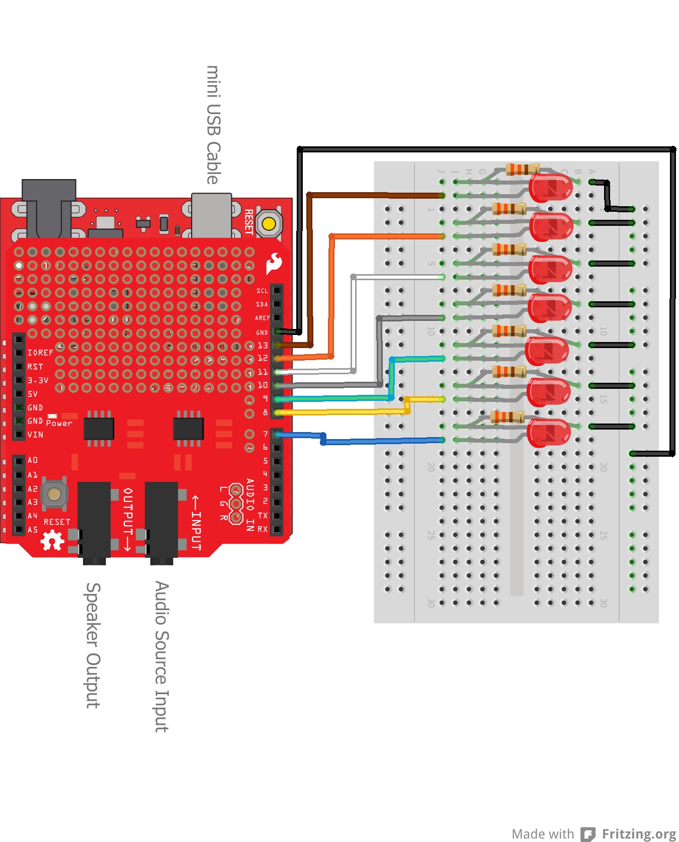
Connect LEDs
For this project, we will use one LED to represent each frequency band. For each LED, run a jumper wire from the RedBoard pin to the positive, anode leg (longer leg) of the LED. From the negative, cathode leg (the shorter leg), run a 330 Ohm resistor to GND. The connections should look like the following:
Spectrum Shield → LED → Resistor → GND
- D7 → LED1 → 330 Ohm → GND
- D8 → LED2 → 330 Ohm → GND
- D9 → LED3 → 330 Ohm → GND
- D10 → LED4 → 330 Ohm → GND
- D11 → LED5 → 330 Ohm → GND
- D12 → LED6 → 330 Ohm → GND
- D13 → LED7 → 330 Ohm → GND
The circuit below shows LEDs of the same color, but feel free to use a different color for each band.
Connect Audio System
At this point, it's time to connect your audio sources. For this example, we are going to hook up a basic MP3 player. Plug one end of an audio cable into the MP3 player, and plug the other end into the "Audio In" jack on the Spectrum Shield.
The second audio cable then provides the audio output to a speaker system. Plug one end into the "Audio Out" jack on the Spectrum shield, and plug the other end into a speaker.
Power the System
You can use an external power supply (such as a wall adapter or 9V battery) if you so desire. For this basic example however, the system will function fine if you power it off of the miniUSB connection on the RedBoard.
Keep in mind if you end up switching out the LEDs for LED strips or an LED matrix, you will most likely need an external power supply. Check the datasheet or hookup guide for any larger displays used.
Final Circuit
Once complete, your circuit should look like the following diagram:
Arduino Code
Basic Arduino Example
Now that you have your hardware all hooked up, it's time to get things blinking!
If you're unsure how to program your Arduino/RedBoard, please check our tutorial here.
We are going to walk through the SparkFun Spectrum Demo sketch. Download that file below, and upload it to your Arduino.
The first thing we must do in our code is set up the RedBoard pins to function properly. The Spectrum Shield pin connections to the RedBoard must be defined, and any pins that will be driving LEDs must also be declared.
language:c
//Declare Spectrum Shield pin connections
#define STROBE 4
#define RESET 5
#define DC_One A0
#define DC_Two A1


//Define LED connections on the Arduino/Shield
int LED[] = {7, 8, 9, 10, 11, 12, 13};

//Define spectrum variables
int freq_amp;
int Frequencies_One[7];
int Frequencies_Two[7];
int i;
Note that we declare the LED pins in an array. This enables us to step through the LED pins using a for loop, which we will discuss later. We also declare two arrays Frequencies_One and Frequencies_Two. These will be used to store the frequencies output by the MSGEQ7 ICs.
In the setup loop, set each LED pin as an output (notice that for loop used to step through each LED pin connection!), and set the initial state of the LEDs to off. The shield pins must also be declared as outputs for the STROBE and RESET pins so we can control the shield using the RedBoard. The DC output pins are each declared as an INPUT in the code, because the RedBoard will be reading data in from these pins. Once the pins are declared, the ICs are initialized by cycling the STROBE and RESET pins as described earlier in the Control Pins section.
language:c
/********************Setup Loop*************************/
void setup() {
  //Set LED pin configurations
  for(i=0; i<7; i++)
  {
    pinMode(LED[i], OUTPUT);
    digitalWrite(LED[i], LOW);
  }

  //Set spectrum Shield pin configurations
  pinMode(STROBE, OUTPUT);
  pinMode(RESET, OUTPUT);
  pinMode(DC_One, INPUT);
  pinMode(DC_Two, INPUT);
  digitalWrite(STROBE, HIGH);
  digitalWrite(RESET, HIGH);

  //Initialize Spectrum Analyzers
  digitalWrite(STROBE, LOW);
  delay(1);
  digitalWrite(RESET, HIGH);
  delay(1);
  digitalWrite(STROBE, HIGH);
  delay(1);
  digitalWrite(STROBE, LOW);
  delay(1);
  digitalWrite(RESET, LOW);
}
For the main section of the sketch, we loop through two user-defined functions. Read_Frequenices() and Graph_Frequencies() tell the RedBoard to read the frequencies coming off the Spectrum Shield, and light up the connected LEDs, respectively.
language:c
/****************Main Function Loop***************************/
void loop() {

  Read_Frequencies();
  Graph_Frequencies();
  delay(50);

}
The Read_Frequencies() function is defined next in the code. This steps through each frequency band on the Spectrum Shield, reading the DC values output, and storing these values into the predefined frequency arrays.
language:c
/*************Pull frquencies from Spectrum Shield****************/
void Read_Frequencies(){
  //Read frequencies for each band
  for (freq_amp = 0; freq_amp<7; freq_amp++)
  {
    digitalWrite(STROBE, HIGH);
    delayMicroseconds(50);
    digitalWrite(STROBE, LOW);
    delayMicroseconds(50);

    Frequencies_One[freq_amp] = analogRead(DC_One);
    Frequencies_Two[freq_amp] = analogRead(DC_Two);
  }
}
The function where the real fun happens is the Graph_Frequencies() function. With this function, the RedBoard drives the LEDs based on the frequencies being read by the Spectrum Shield.
We have included two different example sketches in the repository, to show different methods of lighting the LEDs. Each will create a different effect, so you can choose which works better for your particular project. In this first example, we compare the two frequencies to see which is larger. We then use the higher DC output as the delay time for turning the LED on. This cycles through each LED, turning them on or off based on the frequency output. This creates a bit of a "Jacob's Ladder" effect with the lights.
language:c
/***********Light LEDs based on frequencies***********************/
void Graph_Frequencies(){
   for( i= 0; i<7; i++)
   {
     if(Frequencies_Two[i] > Frequencies_One[i]){
        digitalWrite(LED[i], HIGH);
        delay(Frequencies_Two[i]);
        digitalWrite(LED[i], LOW);
     }
     else{
        digitalWrite(LED[i], HIGH);
        delay(Frequencies_One[i]);
        digitalWrite(LED[i], LOW);
     }
   }
}
If instead you would prefer to have all the LEDs on at the same time and have the lights brighten or dim based on the frequency outputs, use the SparkFun PWM Demo instead.
In this sketch, the LEDs are all turned on, but as the RedBoard cycles through each frequency channel, the RedBoard uses PWM to control the brightness of each LED. The frequency values are mapped from the 0-1023 analog readings to the 0-255 range that Arduinos can use for the analogWrite function. This creates a pulsing light effect on all of the LEDs.
language:c
/***************Light LEDs based on frequencies******************/
void Graph_Frequencies(){
   for( i= 0; i<7; i++)
   {
     if(Frequencies_Two[i] > Frequencies_One[i]){
        analogWrite(LED[i], Frequencies_Two[i]/4);
     }
     else{
        analogWrite(LED[i], Frequencies_One[i]/4);
     }
   }
}
Keep in mind to use this example, you must have your LEDs hooked up to pins that are capable of PWM. You can find more information about which pins have this functionality on the Arduino boards here.
Additional Examples
There are plenty of projects out there using the Spectrum Shield, so do a bit of searching if you need some more inspiration! Bliptronics, the collaborator on the Spectrum Shield wrote a great Arduino example that works with the Spectrum Shield and an LED matrix. The sketch is included here for reference, but you can also find it in the GitHub repository.
language:c
#include <LEDPixels.h>

//Example to control RGB LED Modules with Spectrum Analyzer
//Bliptronics.com
//Ben Moyes 2010
//Use this as you wish, but please give credit, or at least buy some of my LEDs!
//


LEDPixels LP;  //Our LEDPixels library - see http://www.bliptronics.com/ArduinoCode/LEDPixels.zip

//For spectrum analyzer shield, these three pins are used.
//You can move pinds 4 and 5, but you must cut the trace on the shield and re-route from the 2 jumpers.
int spectrumReset=5;
int spectrumStrobe=4;
int spectrumAnalog=0;  //0 for left channel, 1 for right.

//This holds the 15 bit RGB values for each LED.
//You'll need one for each LED, we're using 25 LEDs here.
//Note you've only got limited memory, so you can only control
//Several hundred LEDs on a normal arduino. Double that on a Duemilanove.

int MyDisplay[25];

// Spectrum analyzer read values will be kept here.
int Spectrum[7];

void setup() {
  byte Counter;

  //Initialize the LEDPixels library.
  //            refresh delay, address of data, number of LEDs, clock pin, data pin.
  LP.initialize(25, &MyDisplay[0],25, 12, 11 );

  //Setup pins to drive the spectrum analyzer.
  pinMode(spectrumReset, OUTPUT);
  pinMode(spectrumStrobe, OUTPUT);

  //Init spectrum analyzer
  digitalWrite(spectrumStrobe,LOW);
    delay(1);
  digitalWrite(spectrumReset,HIGH);
    delay(1);
  digitalWrite(spectrumStrobe,HIGH);
    delay(1);
  digitalWrite(spectrumStrobe,LOW);
    delay(1);
  digitalWrite(spectrumReset,LOW);
    delay(5);
  // Reading the analyzer now will read the lowest frequency.

  // Turn all LEDs off.
  LP.setRange(0,24,LP.color(0,0,0));
  LP.show();                             //Write out display to LEDs

}

void loop() {

  int Counter, Counter2, Counter3;

  showSpectrum();
  delay(15);  //We wait here for a little while until all the values to the LEDs are written out.
              //This is being done in the background by an interrupt.
}

// Read 7 band equalizer.
void readSpectrum()
{
  // Band 0 = Lowest Frequencies.
  byte Band;
  for(Band=0;Band <7; Band++)
  {
    Spectrum[Band] = (analogRead(spectrumAnalog) + analogRead(spectrumAnalog) ) >>1; //Read twice and take the average by dividing by 2
    digitalWrite(spectrumStrobe,HIGH);
    delayMicroseconds(50);
    digitalWrite(spectrumStrobe,LOW);
    delayMicroseconds(50);
  }
}


void showSpectrum()
{
  //Not I don;t use any floating point numbers - all integers to keep it zippy.
   readSpectrum();
   byte Band, BarSize, MaxLevel;
   static unsigned int  Divisor = 80, ChangeTimer=0; //, ReminderDivisor,
   unsigned int works, Remainder;

  MaxLevel = 0;

  for(Band=0;Band<5;Band++)//We only graph the lowest 5 bands here, there is 2 more unused!
  {
  //If value is 0, we don;t show anything on graph
     works = Spectrum[Band]/Divisor;    //Bands are read in as 10 bit values. Scale them down to be 0 - 5
     if(works > MaxLevel)  //Check if this value is the largest so far.
       MaxLevel = works;
     for(BarSize=1;BarSize <=5; BarSize++)
        {
        if( works > BarSize) LP.setLEDFast( LP.Translate(Band,BarSize-1),BarSize*6,31-(BarSize*5),0);
          else if ( works == BarSize) LP.setLEDFast(    LP.Translate(Band,BarSize-1),BarSize*6,31-(BarSize*5),0); //Was remainder
            else LP.setLEDFast( LP.Translate(Band,BarSize-1),5,0,5);
        }
  }
  LP.show();

 // Adjust the Divisor if levels are too high/low.
 // If  below 4 happens 20 times, then very slowly turn up.
  if (MaxLevel >= 5)
  {
    Divisor=Divisor+1;
    ChangeTimer=0;
  }
  else
    if(MaxLevel < 4)
    {
      if(Divisor > 65)
        if(ChangeTimer++ > 20)
        {
          Divisor--;
          ChangeTimer=0;
        }
    }
    else
    {
      ChangeTimer=0;
    }
  }
You will need to install the LEDPixels library in order to use the original designer example. The most up-to-date library is available here, or you can download the zip here.
If you need a reminder as to how to install an Arduino library, please check out our tutorial here.
Resources and Going Further
Going Further
Now that you've successfully analyzed the spectrum using your shield, it's time to build your own project!
Try interfacing the Spectrum Shield with an RGB LED Panel, or a MEMS Microphone Breakout, and see what awesome displays you can create!
If you have any questions, please visit our forum.
Additional Resources
Check out these additional resources for more information and other project ideas.
- MSGEQ7 Datasheet
- Spectrum Shield GitHub Repository
- Sound and Motion Reactivity for Wearables
- The Harmonic Skew Zoetrope
- The ElectricBone
- Interactive Hanging LED Array
Also worth checking out is this edition of Engineering Roundtable, which details how to use the Spectrum Shield to control fire!