Spectrum Shield Hookup Guide (v2)
 Toni_K, santaimpersonator
 Introduction
Have you ever wanted to have your project react to music? Then this is the product for you! The Spectrum Shield provides your Arduino board with the capability of measuring a stereo audio input across 7 frequency bands. By reading the amplitude of each band with the ADC of your Arduino board, the users can control how attached devices respond to the audio input.
Materials Required
To follow along with this tutorial, we recommend the following items.

Required Tools
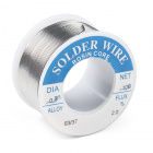
Some assembly is required for this product. You will need a soldering iron, solder, and/or general soldering accessories to solder on headers to your Spectrum Shield.


Additional Accessories
Below is a sample selection of our other headers and soldering tools in our catalog that you may be interested in. For a full selection of our available Headers or Soldering Tools, click on the associated link.


Suggested Reading
We recommend you be familiar with these resources before continuing on with this hookup guide.
How to Solder: Through-Hole Soldering
Serial Communication
Connector Basics
Analog to Digital Conversion
What is an Arduino?
Installing Arduino IDE
Integrated Circuits
Analog vs. Digital
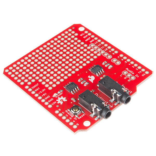
Hardware Overview
Audio Connections
Audio Jacks
The Spectrum Shield contains two stereo audio jacks on the board. The first audio jack, is the input jack (labeled Input). This allows users to input audio from any device -- such as an MP3 player, or cellular phone -- using a basic audio cable. This connection does not have to be used, as there is another option for adding audio input, at the "Audio In" headers, described below.
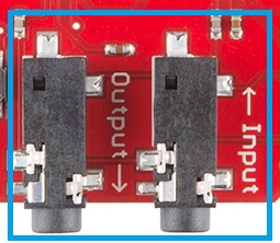
The second audio jack is the audio output, labeled Output. This jack allows you to pass the audio back out to a speaker or other audio system, while the sound levels are being processed by the Spectrum Analyzer ICs. (*Technically, both audio jacks and the audio header are all tied together and can be used as either an input or output.)
Audio In Header
For some projects, you may not be piping audio from a pre-processed source such as a cell phone. For users who want to use things like a MEMS Mic Breakout or the Sound Detector as an audio source, there are three header pins that provide an alternative connection method to your shield.
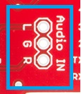
These pins are as follows:
- L = Left Audio Input
- G = Ground Audio Input
- R = Right Audio Input
With both the left and right inputs, you can use stereo devices on these headers. The signals also passes through to the Input and Output audio jacks.
MSGEQ7 ICs
The real power of this shield comes from the two MSGEQ7 ICs on the board. These are CMOS chips, which are seven band graphic equalizers.
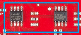
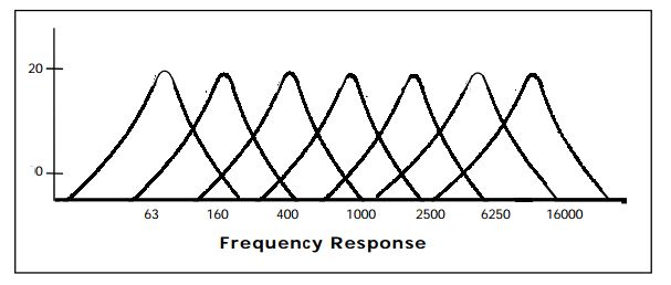
Upon receiving an audio signal in, these ICs split the the spectrum into seven bands, splitting it at the following frequencies:
- 63Hz
- 160Hz
- 400Hz
- 1kHz
- 2.5kHz
- 6.25kHz
- 16kHZ
For the visual learners, here's the frequency graph from the MSGEQ7 datasheet:
Once the spectrum has been split into these ranges, each band is peak detected and multiplexed. The DC output is a representation of the amplitude of each frequency band. Using the strobe and reset pins on the ICs allows the user to select the DC peak output.
Shield Connections
There are 4 main pins that the Arduino/RedBoard or other microcontroller connect to the Spectrum Shield.
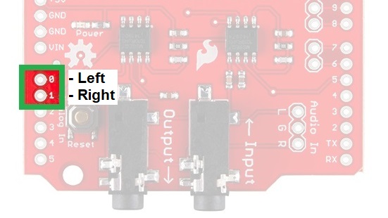
Analog Pins -
There are two analog pins connected to the MSGEQ7 ICs. A0 is the DC analog output from the first IC for the left audio channel, while A1 is the DC analog output from the second, right audio channel.
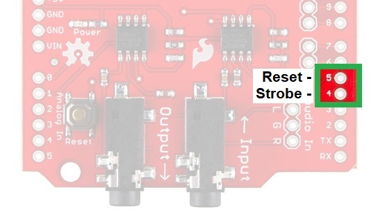
Control Pins -
The control pins connect to the Strobe and Reset pins on the MSGEQ7; D4 and D5, respectively. In order to enable the Strobe pin, you must pull the Reset pin LOW. To reset the entire multiplexer, pull the Reset pin HIGH.
The Strobe pin, once activated, cycles through each of the channels. After the initial pulse, it starts at 63Hz, pulses each channel until 16kHz, and then repeats, starting back at 63Hz. The DC output for each channel will follow the Strobe pulse.
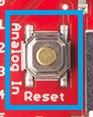
Reset Button
The reset button allows you to reset your Arduino/RedBoard while the shield is inserted. Holding the reset button will pull the reset pin of the ATMega328 (or other microcontroller) low, allowing a system reset. This will restart any sketches currently running on the microcontroller.
Hardware Assembly
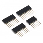
Solder Headers
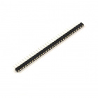
As with any shield, the first step is to choose a header type. We recommend the stackable headers if you need to stack on other shields; otherwise, the (straight) male headers are the simplest to work with. Feel free to choose any connection method you prefer, but remember that his shield uses the Arduino Uno R3 form factor or footprint when selecting your headers.
How to Solder: Through-Hole Soldering
Arduino Shields v2
You will need to solder the headers to the shield, so make sure you have all the appropriate supplies before you begin. If you aren't sure how to solder on the headers to the shield, please check out our How to Solder and Arduino Shield tutorials (also linked above).
Once completed, connect the shield to your microcontroller; if you are using Arduino Uno or SparkFun RedBoard, stack the shield on top.
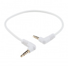
Connect Audio System
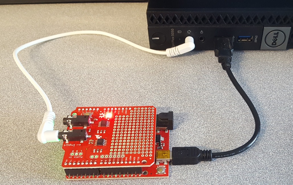
In the following example, we will be using your computer as the audio source. Plug one end of the audio cable into the audio jack on your computer and the other end into the Input jack on the Spectrum Shield. Feel free to use the Output jack on the Spectrum shield to pass the audio out to a speaker or set of headphones.
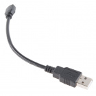
Connecting to the Computer
The last thing you will need to do is attach the microcontroller to the computer (with a USB cable). If you have done everything correctly, it should resemble the image below.
Arduino Example Code
Note: This tutorial assumes you are using the latest version of the Arduino IDE on your desktop. If this is your first time using Arduino, please review our tutorial on installing the Arduino IDE.
Serial Plotter Example
Now that you have your hardware all hooked up, it's time to analyze some audio signals. Below, we will walk through the SparkFun_Spectrum_Shield_Serial_Plotter_Demo.ino sketch. To begin, download that sketch from the GitHub Repository, and upload it to your Arduino. (*The .zip folder must be extracted and the file for the sketch is located in the Spectrum_Shield > Firmware > SparkFun_Spectrum_Serial_Plotter_Demo folder.)
Code Overview
The start of the demo code defines the pins functionality. The Spectrum Shield pin connections to the microcontroller must be defined.
language:c
//Declare Spectrum Shield pin connections
#define STROBE 4
#define RESET 5
#define DC_One A0
#define DC_Two A1

//Define spectrum variables
int freq_amp;
int Frequencies_One[7];
int Frequencies_Two[7];
int i;
Note that we declare two arrays Frequencies_One[] and Frequencies_Two[]; these will be used to store the output of the seven frequency bands from the MSGEQ7 ICs. (*The freq_amp and i variables are counters used for iterations in the code and carry minimal significance.)
In the setup loop, the shield pins must also be declared as OUTPUTs for the STROBE and RESET pins so we can control the shield using the RedBoard. The DC analog pins are each declared as an INPUT in the code, because the RedBoard will be reading data in from these pins. Once the pins are declared, control pins (STROBE and RESET) are set to a LOW condition/output. A delay is added for the settings to take effect, then the serial output is initialized to a 9600 bps bard rate.
language:c
/********************Setup Loop*************************/
void setup() {
  //Set spectrum Shield pin configurations
  pinMode(STROBE, OUTPUT);
  pinMode(RESET, OUTPUT);
  pinMode(DC_One, INPUT);
  pinMode(DC_Two, INPUT);

  //Initialize Spectrum Analyzers
  digitalWrite(STROBE, LOW);
  digitalWrite(RESET, LOW);
  delay(5);

  Serial.begin(9600);
}
For the main section of the sketch, we loop through two user-defined functions. Read_Frequenices() and Graph_Frequencies() tell the RedBoard to read the frequencies coming off the Spectrum Shield, and serial print out the analog values, respectively.
language:c
/****************Main Function Loop***************************/
void loop() {

  Read_Frequencies();
  Graph_Frequencies();
  delay(50);

}
The Read_Frequencies() function is defined next in the code. When called, the function initializes/resets the ICs by cycling the RESET pin as described earlier in the Control Pins section. Then, the function steps through each frequency band on the Spectrum Shield using the STROBE pin, reads the DC analog outputs, and stores the values into the predefined frequency arrays.
language:c
/*************Pull frquencies from Spectrum Shield****************/
void Read_Frequencies() {
  digitalWrite(RESET, HIGH);
  delayMicroseconds(200);
  digitalWrite(RESET, LOW);
  delayMicroseconds(200);

  //Read frequencies for each band
  for (freq_amp = 0; freq_amp < 7; freq_amp++)
  {
    digitalWrite(STROBE, HIGH);
    delayMicroseconds(50);
    digitalWrite(STROBE, LOW);
    delayMicroseconds(50);

    Frequencies_One[freq_amp] = analogRead(DC_One);
    Frequencies_Two[freq_amp] = analogRead(DC_Two);
  }
}
The data is retrieved through the Graph_Frequencies() function. With this function, the RedBoard returns the analog value for the frequencies being read by the Spectrum Shield through the serial port.
language:c
/*****************Print Out Band Values for Serial Plotter*****************/
void Graph_Frequencies() {
  for (i = 0; i < 7; i++)
  {
//    Serial.print(Frequencies_One[i]);
//    Serial.print(" ");
//    Serial.print(Frequencies_Two[i]);
//    Serial.print(" ");
    Serial.print( (Frequencies_One[i] + Frequencies_Two[i]) / 2 );
    Serial.print("    ");
  }
  Serial.println();
}
Code Operation
With the sketch uploaded to your board, you are now able to analyze the different frequency bands of your audio input. Pull, up the Serial Monitor and set the baud rate to 9600. Then, using your computer play an audio sample. You should see the numbers in the columns of the Serial Monitor change with the audio.
Below, are some audio samples that users can use to test the Spectrum Shield:
- Online Tone Generator - a website based tone generator.
- Youtube Video - increases the (audio) signal frequency from 20 Hz to 20kHz.
Try playing the Youtube video and using the Serial Plotter of the Arduino IDE. You should see a response curve similar to the one below. Notice how the shapes resemble the figure from the datasheet in the Hardware Overview section.
Additional Examples
There are plenty of projects out there using the Spectrum Shield, so do a bit of searching if you need some more inspiration! Additionally, you can refer to the original tutorial, which provides other examples including one from Bliptronics, the collaborator on the Spectrum Shield, which works with the Spectrum Shield and an LED matrix.
Resources and Going Further
For more information, check out the resources below:
- Schematic (PDF) - PDF of the Schematic
- Eagle Files (ZIP) - ZIP file with Eagle Files
- MSGEQ7 Datasheet - PDF of Datasheet
- GitHub Product Repo - Hardware and Firmware files.
- SFE Product Showcase
Also worth checking out is this edition of Engineering Roundtable, which details how to use the Spectrum Shield to control fire!