SparkPunk Sequencer Theory and Applications Guide
 Byron J.
Simple Modifications
With the knowledge of the sequencer internals from the previous section, we can explore some modifications and more advanced uses of the sequencer.
We'll start with some simple modifications that don't require much effort, or very much external hardware.
Sequence Length Adjustment
The CD4017 IC at the heart of the Sequencer has ten outputs. While ten is the basis for decimal counting, it's not always the obvious choice for musical composition - four, six or eight steps are much more common musical time signatures. As we mentioned in the hookup guide, the length of the sequence can be constrained to shorten the sequence.
The CD4017 has a pin that resets the internal counter. By feeding one of the step voltages back to that pin, we can constrain the sequence to a shorter range.
The Sequencer PCB has ten pairs of pads across the lower right edge. The step voltage from each step is present on the top pad, and the bottom pad is the counter reset. If you connect the top pad to the bottom pad, it causes the sequence to reset when that step is selected. For instance, if you short the Step Out 9 pad to the adjacent Seq Reset pad, when step 9 is selected, it will cause the sequence to reset to the first step, effectively limiting the sequence to 8 steps.
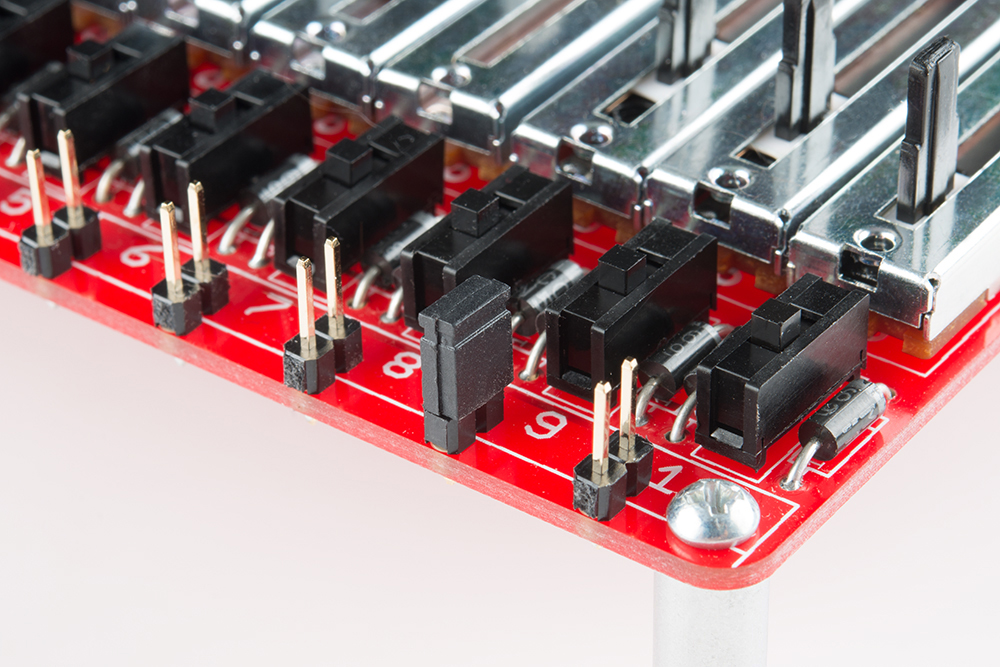
You can make the connection between the pads a number of different ways. If you wanted the constraint to be permanent, you could solder in a short piece of wire. For a manually adjustable limit, snap breakaway headers off into 2-pin pairings, and solder them into each pair of pads. Then you can use jumper shunts to bridge them.
One-Shot Sequence Playback
Similar to the reset pin on the CD4017, there is an asynchronous set pin on the flip-flop that latches the play button (recall that the Q output from the flip-flop is the source of the "stop" signal). If we route a step voltage to that pin, we can cause the sequence to stop itself when that step is reached.
This is easy do do using the pads near the CD4013, marked ONCE. Again, you can use a 2-pin header or a switch to make the connection.
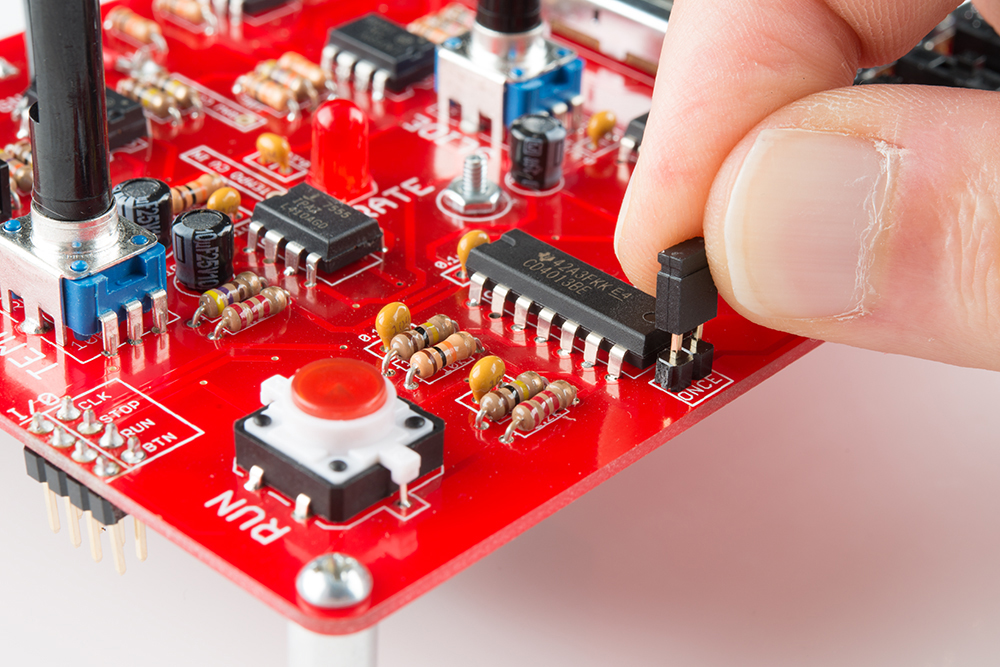
This works in conjunction with the "last step" setting described above -- a last step is selected, and the sequence will run once, halting when it reaches that step. Because the flip-flop requires a pulse to set it, there is no easy way to do this with a full set of ten steps, as there is no additional pluse to indicate it has moved beyond the tenth step.
Component Values
Tempo Clock
The tempo clock is based around the parallel combination of C2 and C4. By changing those caps, we can change the rate of sequence playback. The equation that governs the frequency is stated in the 7555 datassheet, as
7555 frequency = 1/(1.4 * R * C)
Where R is the series combination of R1 and RV1, adjustable between 470 Ω and 10,470 Ω, and C is 20 µF, the parallel combination of C2 and C4
Because we're dividing the 7555 clock in half, the actual tempo clock is half that
clock frequency = (7555 frequency/2)
This results in a range of about 1.5 Hz at the lowest, to 35 Hz at the highest.
To make the clock run slower, increase the capacitance. Lowering the capacitance will raise the frequency.
Slide Time
Similarly, we can change the maximum slide time by adjusting cap C3. Again, larger values will take longer to charge, lengthening the slide. Reducing the time with smaller values is probably not terribly useful, as we can already adjust the time downwards with potentiometer RV2.
Colored LEDs
If red is not to you liking, you can switch out the LEDs for other colors. The board was fits regular 5mm (AKA T-1 3/4) LEDs. We offer them in many colors, including red, yellow, blue, and green. You may need to substitute different resistors for the series 2.2K Ω, to adjust the brightness.