SparkPunk Sequencer Theory and Applications Guide
Interfacing With More Hardware
Heads Up!
We're working our way into more advanced territory. The sections below are a more adventurous than anything we've touched on yet, and involve desoldering, modifications to the PCB, and more detailed troubleshooting skills. Some of the descriptions are purposefully vague, as an exercise for more knowledgable users.
Synchronizing Multiple Sequencers
If you were following the theory of operations carefully, you probably noticed that when the text described the signals run, stop, clock, and button, the signals in the schematic were actually marked "out" and "in," with a jumper connecting them. These signals are intended to be broken up that way so they can be easily routed between multiple sequencers.
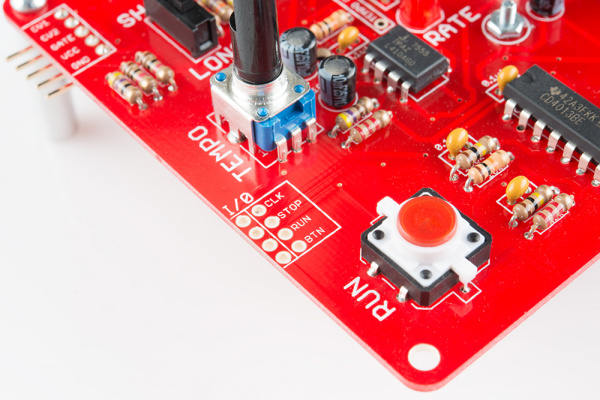
Those signals are all present in the synchronization interface, on the left edge between the run button and tempo knob. The following table denotes the behavior of each of those signals exhibits.
| Signal | As Output | As Input |
| CLK | Pulses at tempo generated by clock system | Causes CD4017 counter to increment |
| STOP | Indicates sequencer is stopped | Resets CD4017 Holds clock divider in reset |
| RUN | Indicates sequence is playing | Allows 7555 to run |
| BTN | Indicates button has been pushed | Pulses cause play/stop to toggle |
In paticular, notice that for the sequencer to advance, the stop line must be low, run line must be high, and clock pulses need to come in on the clock line.
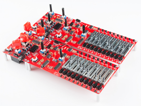
The most obvious way to use this port is to synchronize multiple sequencers. One acts as the master clock, with other sequencers following (or "chasing") that clock.
Modifications
If you have two sequencers, it's not hard to modify them to use the synchronization port. Select one to be the the master clock, and the other to follow that clock.
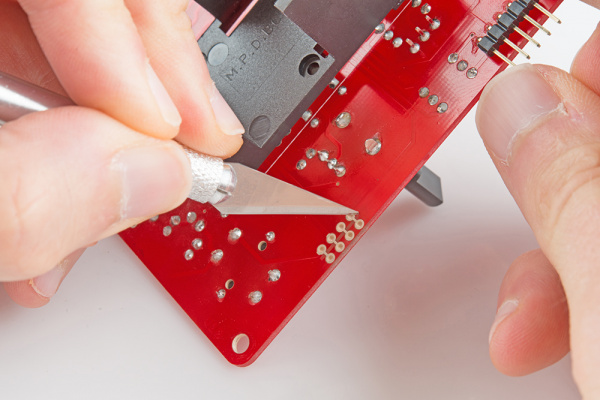
First, on the slave sequencer, cut the copper traces that run between the columns of the synch port.
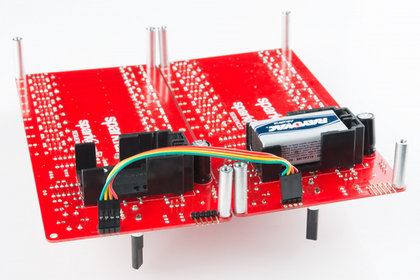
Then run wires from the pads in the "O" (output) column on the master sequencer to the "I" (input) column on the slave. We're using snappable headers and 4-pin jumper wires, so we can easily disconnect the units later.
You'll also need to join the grounds of both sequencers together. It's easiest to tack-solder a short length of wire to the "GND" pin of the 9V battery box on one sequencer, and run it to the same point on the other.
You can also connect the nearby 9V terminals, so that you only need a single battery to power the whole conglomeration, but it will eat batteries twice as fast.
Now, when you press play on the master, both sequencers will start and run together.
One clock master can drive multiple slaves, if you connect the slave synch input ports in parallel with each other.
To make a sequencer that can convert between being a master and slave, you can use normalled jacks, or install two pins from a snappable header and use jumper shunts to reconnect the pins.
Power
As you start to stack up multiple SparkPunks and Sequencers, you start to wind up against the limits of what a 9V battery can reliably power. The first symptom of insufficient power is that the long/short gate feature stops working reliably.
If you'd like to avoid batteries altogether, you can substitute a 9V wall adapter. Each Sequencer & SparkPunk pair draw a maximum of about 20 mA, so that adapter should be good for many, many pairs. The best way to connect it is using a star topology, with each sequencer having a dedicated power and ground cables back to the power supply, rather than daisy-chaining power to multiple sequencers.
Other Synthesizers
One last modification worth mentioning is to use the Sequencer with other synthesizers.
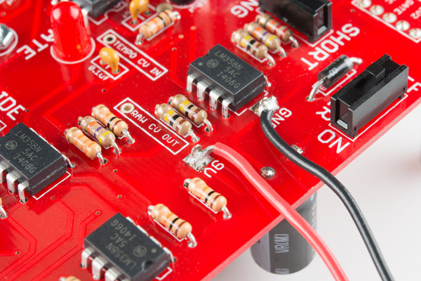
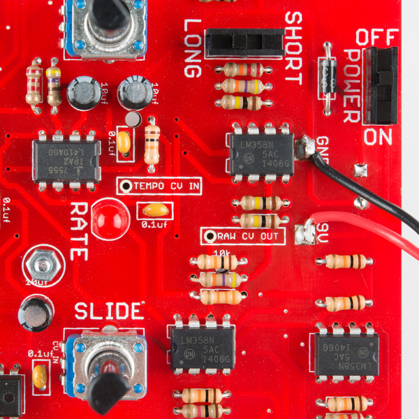
As we reviewed in the description of the control voltage interface, the main control voltage output is inverted - a higher voltage results in a lower frequency from the Sound Generator. This is counter-intuitive, and also the opposite of the convention used by most other synthesizers. Regular analog synthesizers with control voltage inputs produce higher frequencies for higher control voltages. This voltage is present inside the Sequencer, and is found on the solder pad marked RAW CV OUT. This is the stage after the slide has been applied, but before the amplifier that inverts it for the SparkPunk.
Before you try this, you should check the specification of the synthesizer you intend to control -- additional circuitry may be needed to get the raw CV scaled into a suitable range. Some synths are limited to a gate of only 5V -- you can use a divider or Zener diode clamp to attenuate the 9V gate into that range.
Tempo CV Input
The eagle eyed reader will have also spotted the TEMPO CV IN pad in the photo above. It is similar to the CV inputs on the Sound Generator -- voltages between ⅓ Vcc and ⅔ Vcc adjust the tempo over about a 2-to-1 range. The response is inverted -- higher voltage results in lower frequency. Exceeding the ⅓ to ⅔ window can cause the 7555 to stutter or stall.
We don't have any specific mods for the Tempo CV, but it is worth mentioning as an option, so someone will sure dream up a use for it!
