SparkPunk Sequencer Hookup Guide
 Byron J.
Usage
We skimmed through the basic functionality of the sequencer while we were testing - you probably already have a good idea what the controls do. But if you'd like to understand it in more detail, then keep reading.
The Controls
The following picture denotes the controls on the sequencer.
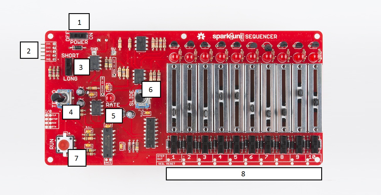
- Power Switch - Turns the the sequencer on and off.
- Sound Generator interface connector - 5-pin header that connects to the SparkPunk Sound Generator. It provides power, pitch, and trigger signals to the attached SparkPunk.
- Long/Short Switch - Determines the length of notes triggered by the sequencer.
LONGnotes sound for the full length of the step, andSHORTnotes are half the step length. We'll illustrate this in more detail below. - Tempo Knob - Controls the clock, determing the rate at which the sequencer advances from step to step.
- Rate LED - Blinks to display the clock rate.
- Slide knob - Controls the time it takes for the sequencer to slide from note to note. See the diagram below for a more detailed description.
- Run switch - Starts the clock, which in turn causes the sequence to advance between steps. It also contains an LED that lights up while the sequencer is running.
- ** 10 steps** - Each step has several controls.
- Step indicator LED - Denoting the active step of the sequence.
- Pitch slider - The pitch control voltage is determined by the slider setting on the active step.
- Trigger switch - When this switch is on, the note for this step will sound, with the length determined the the
SHORT/LONGswitch. If the trigger is off, this step of the sequence will be silent.
An analog sequencer like this is intended to be a hands-on, interactive musical tool. Having physical controls makes it easy and fun to experiment with compositional ideas.
Sound Generator Interface
The heart of the sequencer is the interface to the Sparkpunk Sound Generator. The sound generator was designed so that it could simply plug into the sequencer.
All of the controls on the Sound Generator still function when connected to the sequencer. The knobs and switches control the sonic parameters, and the trigger switch triggers sounds. At the same time, the sequencer controls the sound generator using two signals, the pitch control voltage and the gate. As the sequence plays, the circuit selects one column of controls at a time, and analog voltages that correspond to the control settings are driven to the output port.
Pitch Control Voltage
The sliders on the sequencer control the pitch of the sound generator. The following diagram illustrates how slider positions are translated to the control voltage output:
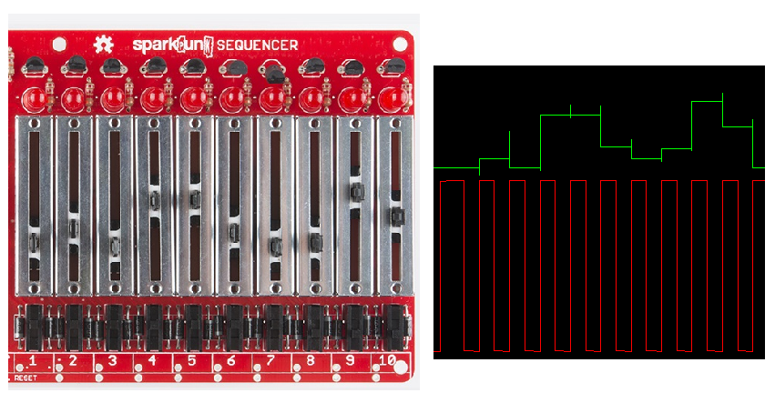
By comparing the slider positions to the green trace, you can see how they are converted into voltages. Each slider is selected in turn when a rising edge is seen on the clock, the red signal.
Slide
You'll notice that the control voltage above changes very quickly when a clock pulse is received - the rise and fall segments are nearly vertical, with the result looking like a series of rectangles. By turning the SLIDE control up, we can slow down those transitions, causing the edges to become rounded, as you see here:
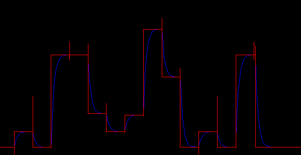
The red plot is the same control voltage pattern we saw above, and the blue is the result of turning up the SLIDE control. The more slide you add, the longer it takes to transition from one pitch to the next. The result of this is a musical effect known as portamento or glissando, which is commonly used by instruments like the trombone or slide guitar.
The slide is generally more audible in the LONG setting than SHORT. To understand why, let's take a look at the gate signal.
Gate
In electronic terms, a "gate" or "gating function" is a DC signal that corresponds to the presence of another signal. It can be generated as an output by a circuit (such as the gate output from the Sound Detector), or as an input to a circuit. In electronic music, a gate signal controls whether a tone generator is running.
The switch on each step of the sequencer allows you to control the gate signal when that step is active. When the switch is off, the gate signal is not driven, and the sound generator will be silent. However, when the gate switch is on, there are two possible results, as determined by the SHORT/LONG switch.
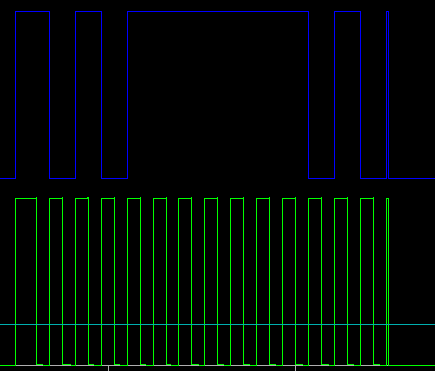
When the switch is set to LONG and the step switch is on, the gate for a step lasts the entire step. In the diagram above, the clock is in green at the bottom, and the gate is in blue at the top. If adjacent steps are on, the gate is continuous - a legato articulation, as shown by the long plateau in the gate signal.
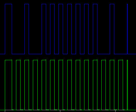
In contrast, a short gate is only half a step long. Even if adjacent steps are on, there will be a half-clock duration of silence between them. In the diagram above, the step switches are set the same as the previous example, but the length switch is set to SHORT. The long plateau has been chopped into a number of small chunks.
Power Sharing
One final item worth noting: both the Sequencer and Sound Generator have battery holders and power switches. The units have a common power bus that allows either device to power the other. Only one battery needs to be installed, and the power switch on the unit with the battery will switch the pair on and off. The bus uses diode protection to keep the batteries from charging each other if both are present.
Diving Deeper
At this point, we've covered the assembly of the SparkPunk Sequencer, and basic usage with the Sound Generator. Like the Sound Generator, the sequencer in intended to be adapted, modified and customized. One of those modifications is both easy and very useful.
A lot of western music built around rhythmic groupings of 4, 6 or 8, so builders might find that the 10-step sequence length is hard to use. Therefore, we'll cover a quick modification, which allows you to shorten the sequence to fewer steps.
Across the lower right edge of the PCB are pairs of solder pads - simply bridge the pair of pads to cause the sequence to reset when that step is reached.
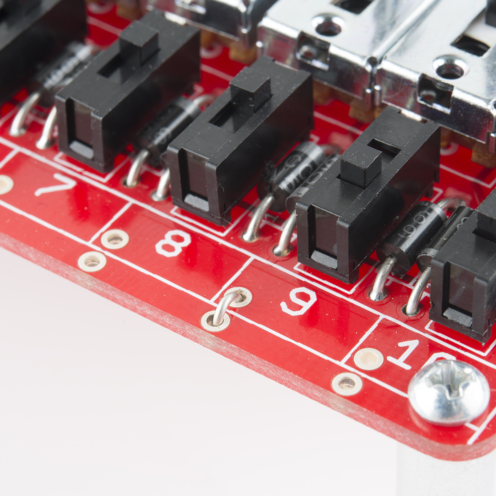
You'll bridge the pads that are one step beyond what you want as the last step - as shown above, a wire on step nine shortens the sequence to 8 steps. If you don't want to make a permanent connection, you can install snappable headers, then use jumper shunts to make the sequence length adjustable.