SparkFun QwiicBus Hookup Guide
 El Duderino,
  Englandsaurus
Hardware Assembly
In this section we'll go over configuring your QwiicBus EndPoint and MidPoint as how to assemble the QwiicBus circuit. Before we start connecting anything there are a couple of things to take note of.
Ethernet Cables
Make sure your Ethernet cables are straight-through (i.e. Pin 1 on one end of the cable is connected to Pin 1 on the other end) and not crossover. Most Ethernet cables sold are straight-through so you probably have nothing to worry about here. If you're not sure what type of Ethernet cable you have, you can test for pin continuity with a digital multimeter.
Also take the voltage drop over the Ethernet cables into account. For longer chains or for circuits with many devices on multiple MidPoints, consider using one of the alternate power configurations so the voltage drop is negligible. The formula below can help you calculate the voltage drop at different lengths of CAT-6/Ethernet cable and whether or not you will need to consider one of the alternate power options:
In this formula, I is the current through the object in Amperes and R is the resistance of the wires in Ohms. Most CAT-6/Ethernet cable will have 24AWG internal wires and depending on the quality of the cable will be either copper or aluminum. Refer to a table like this one from PowerStream to determine the resistance in Ω/1000ft or Ω/km to help calculate the approximate voltage drop.
I2C Pull-Up Resistors
Take time to note which devices you will have connected to your EndPoint and MidPoint's I2C bus side have their pull-up resistors enabled and what voltage they are tied to. Almost all Qwiic products have pull-up resistors enabled by default that pull the SDA/SCL lines connected directly to the I2C bus to 3.3V.
The PCA9615 requires pull-up resistors on the two-wire I2C bus so each EndPoint and MidPoint must have at least one pair of pull-up resistors enabled on the two-wire side. The pull-up resistors do not translate through to the differential side of the PCA9615. To help make things a bit simpler, each QwiicBus EndPoint and MidPoint come with pull-up resistors on both SDA and SCL lines tied to VDDA. Normally, VDDA is 3.3V but can be as high as 5V on the EndPoint depending on the power configuration settings.
Power Configuration Settings
As we mentioned in the Hardware Overview section of this guide, both QwiicBus boards feature a plethora of jumpers as well as two pairs of dedicated power PTH pins to configure how to power your QwiicBus circuit. Let's take a closer look at the three options available for powering the QwiicBus.
Default - Entire System at 3.3V
In this configuration, the entire system is powered at 3.3V and the buck regulator(s) on the MidPoint(s) are unpowered. On the MidPoint(s), the Bypass jumper is CLOSED and both sides of the PSEL jumper are OPEN. 3.3V is provided either from your development board or single-board computer through the Qwiic connector or the 3.3V pin on the primary EndPoint.
Take note, in this configuration where all power is provided over the CAT-6/Ethernet cables, your total current draw will for attached devices will be limited to ~550mA with standard CAT-6/Ethernet cables due to the physical constraints of the wires inside. Anything beyond 550mA runs the risk of damaging the wires and can create a fire hazard.
The 3.3V supply voltage is then transferred from the initial EndPoint over the CAT-6/Ethernet cables in your QwiicBus system. Note that over long lengths of wire, you will see voltage drop and devices further down your QwiicBus chain may misbehave if the voltage drops below their operating range. Refer to the formula and links in the Ethernet Cables subsection above for calculating the voltage drop in your circuit.
Alternate 1 - VCC1 at 5V
While the default 3.3V configuration should work just fine for shorter QwiicBus chains, we found the PCA9615 functions better when powered with 5V. Powering VCC1 with 5V also allows us to also use the buck regulator on the MidPoint to source up to 3A@3.3V to devices connected to the MidPoint. Using this configuration requires adjusting both the EndPoint and MidPoint as well as multiple power supplies.
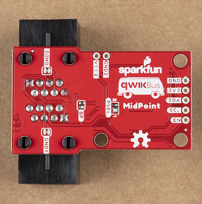
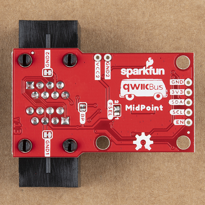
First and most importantly, the Bypass jumper on each MidPoint must be OPEN. On each MidPoint, adjust the PSEL jumper to the "1" side (see image below).
It is also strongly recommended to OPEN the 0-1 jumper on the primary / first EndPoint to isolate VCC (VDDA) from VCC1 (VDDB) but leave the 0-1 jumper on the terminating EndPoint CLOSED. Leaving the 0-1 jumper closed will send 5V to any Qwiic devices attached to your terminating / last EndPoint.

With the jumpers adjusted and your QwiicBus circuit assembled including any peripheral devices attached to your MidPoint(s), connect your 5V source to the VCC1 and GND PTH pins on the primary EndPoint. If the 0-1 jumper is opened, 3.3V should be provided over the Qwiic connectors or through the 3.3V PTH pin to power VCC (VDDA) on the primary EndPoint.
Alternate 2 - VCC2 at 3.8V to 36V
For this configuration, we use two separate voltages to power the EndPoints and MidPoint(s). First and most importantly, the Bypass jumper on each MidPoint must be OPEN. Adjust the PSEL jumper to the "2" position on each MidPoint.
If you plan to power VCC1 with 5V it is recommended to OPEN the 0-1 jumper on the primary EndPoint to isolate VCC from VCC1. As covered above, we recommend leaving the 0-1 jumper CLOSED on the terminating EndPoint.
After adjusting the jumpers and assembling your QwiicBus circuit including any peripheral devices attached to your MidPoint(s), connect 3.8V to 36V to the VCC2 and GND2 PTH pins on the primary EndPoint. 3.3V for the first EndPoint should be provided from the microcontroller/SBC via the Qwiic connectors or a dedicated source through the 3.3V PTH pin.
Alternate 3 - VCC1 at 5V and VCC2 at 6V to 36V
This advanced configuration uses multiple power supply to allow for optimal performance of the QwiicBus over very long distances with multiple MidPoints. As mentioned above, we have found the QwiicBus operates best over long distances at 5V (particularly VDDB @5V). In this configuration, VCC1 is powered with 5V and VCC2 is powered with 6V-36V. Before connecting power supplies, a few jumpers must be adjusted.
First, the Bypass jumper on each MidPoint must be OPEN. Set the PSEL jumper on all MidPoints to the "2" position. The 0-1 jumper on the primary EndPoint is OPEN and the 0-1 jumper on the terminating EndPoint is CLOSED. This isolates VDDA and VDDB on the first EndPoint so the Qwiic connectors on the first EndPoint are at 3.3V. As we mentioned before, the Qwiic connectors and 3.3V PTH pin on the terminating EndPoint will be at 5V so be careful what is connected to that EndPoint.
After adjusting jumpers on all the QwiicBus boards and assembling the rest of your circuit (including connecting any Qwiic devices to MidPoints/EndPoints), connect the 5V power supply to the VCC1 and GND PTH pins and the power supply sourcing 6V to 36V to the VCC2 and GND2 PTH pins to the primary EndPoint.
Assembling the QwiicBus Circuit
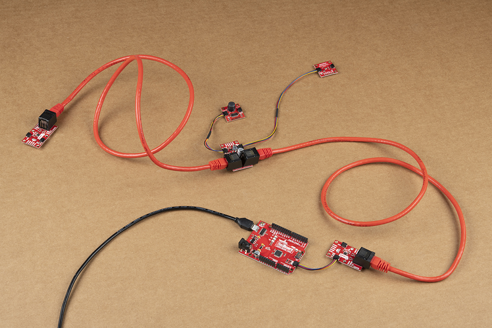
After taking into consideration how you intend to configure your QwiicBus circuit it's time to assemble it. Adjust the appropriate jumpers (if necessary), connect your controller (Arduino/SBC) to the primary EndPoint along with any Qwiic/I2C devices to the EndPoints and MidPoint(s) and connect the QwiicBus boards to each other with Ethernet cable plugged into the RJ-45 connectors on each board. Once the devices are all connected together, power up the circuit. The photo below shows the QwiicBus assembled in the default configuration (all boards powered with 3.3V) so your circuit may differ.
With everything adjusted and connected properly, that's all you need to assemble your QwiicBus circuit. Go forth and build ridiculously long, wired I2C circuits to your heart's content!