SparkFun QwiicBus Hookup Guide
Contributors:
 El Duderino,
  Englandsaurus
El Duderino, Englandsaurus 
Resources and Going Further
Now that you have your QwiicBus set up and configured to your liking, it's time to start creating some I2C device networks! For more information, take a look at the following links:
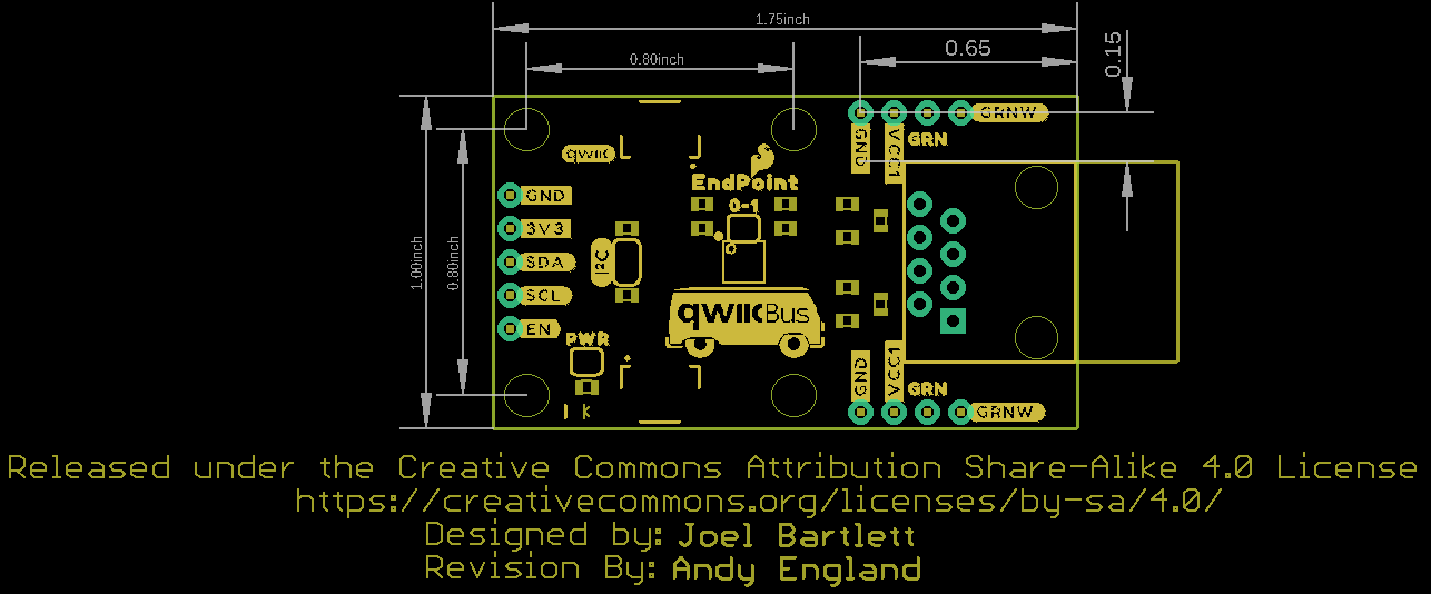
QwiicBus EndPoint Links
- Schematic (PDF)
- Eagle Files (ZIP)
- Dimensional Drawing (PNG)
- PCA9615 Datasheet (PDF)
- Hardware GitHub Repository
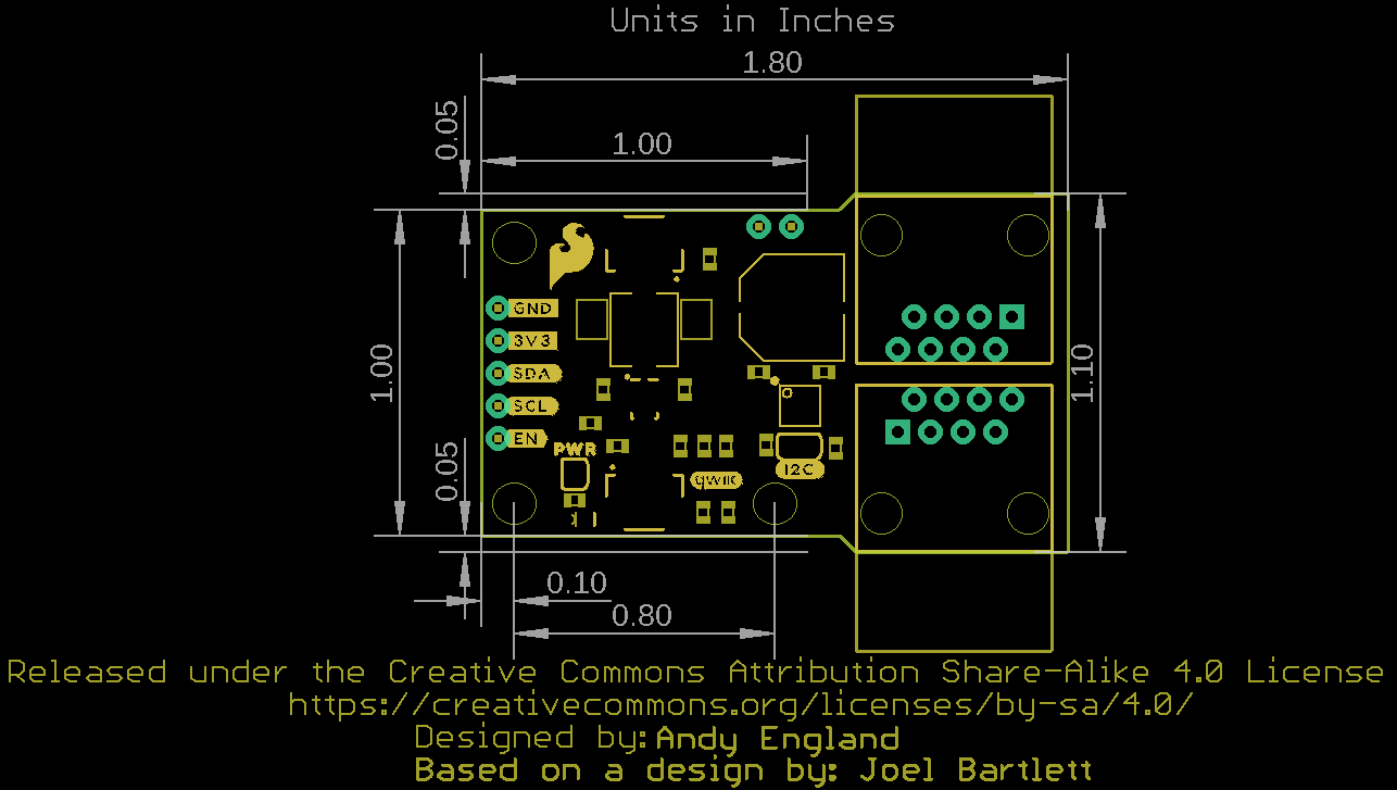
QwiicBus MidPoint Links
- Schematic (PDF)
- Eagle Files (ZIP)
- Dimensional Drawing (PNG)
- LMR33630 Datasheet (PDF)
- Hardware GitHub Repository
Read more about Farmhand's QwiicBus story and other agriculture tech projects from SparkFun in the following links:
- Farmhand: Building a Custom Solution for Farming
- SparkFun Agriculture Tech Landing Page
- Precision Agriculture and Evironmental Monitoring Technology Blog Post
For inspiration for your I2C project using the QwiicBus, check out the following tutorials:
Basic Servo Control for Beginners
An introductory tutorial demonstrating several ways to use and interact with servo motors!
SparkFun Top pHAT Hookup Guide
The pHAT to sit above your other HATs. Does that make it the "king" of the pHATs?
This guide will help you get started using the Top pHAT with the Raspberry Pi.
Qwiic Haptic Driver DA7280 Hookup Guide
The Qwiic Haptic Driver includes an itty-bitty, Linear Resonant Actuator (LRA) vibration motor and Dialog Semiconductor's DA7280 motor driver IC for applications that require haptic feedback.
SparkFun Absolute Digital Barometer - LPS28DFW (Qwiic) Hookup Guide
Get started adding water-resistant pressure sensing using the SparkFun Absolute Digital Barometer - LPS28DFW (Qwiic) following this guide.