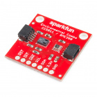
SparkFun Qwiic AS3935 Lightning Detector Hookup Guide
This Tutorial is Retired!
This tutorial covers concepts or technologies that are no longer current. It's still here for you to read and enjoy, but may not be as useful as our newest tutorials.
View the updated tutorial: SparkFun AS3935 Lightning Detector Hookup Guide (v20)
Introduction
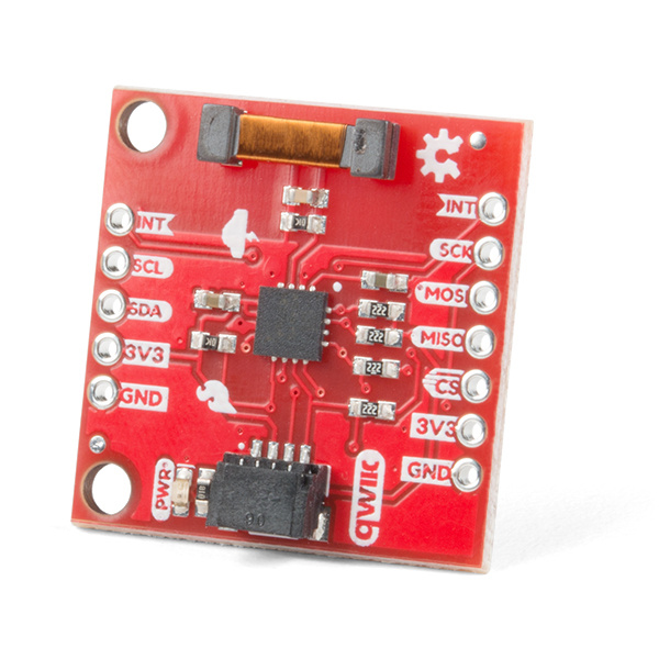
The SparkFun Qwiic AS3935 Lightning Detector adds lightning detection to your next weather station or to your next bike ride. Are you worried about the looming clouds in the distance, how far away is that storm exactly? The lightning detector can tell you the distance to the front of the storm 40 km away with an accuracy of 1km. It has false positive rejection and comes with many configurable features. To get at those features we have written a library that gives you access to settings such as storm sensing sensitivity when detecting indoors vs outdoors, or the number of lightning strikes needed to trigger an interrupt! The board supports both I2C and SPI, and so we've whipped out the Qwiic connector to make this easy to integrate into the Qwiic environment.
Required Materials
To follow along with the example code used in this tutorial, you will also need the following materials. You may not need everything though depending on what you have. Add it to your cart, read through the guide, and adjust the cart as necessary.
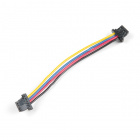
Qwiic Cable - 50mm
PRT-14426If you need different size Qwiic cables we offer a kit that contains many sizes but we also carry them individually as well:
Qwiic Cable - 100mm
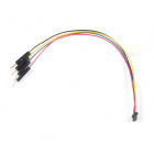
PRT-14427Qwiic Cable - Breadboard Jumper (4-pin)
PRT-14425Qwiic Cable - 500mm
PRT-14429Tools
Depending on your setup, you will may need a soldering iron, solder, and general soldering accessories.
Suggested Reading
If you aren't familiar with the Qwiic system, we recommend reading here for an overview.
 |
| Qwiic Connect System |
We would also recommend taking a look at the following tutorials if you aren't familiar with them.
Serial Peripheral Interface (SPI)
I2C
How to Work with Jumper Pads and PCB Traces
RedBoard Qwiic Hookup Guide
Hardware Overview
Power
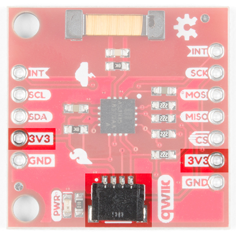
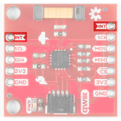
You can provide 3.3V through the Qwiic connector on the board or through the 3V3 labeled pin on the through hole header. When you correctly power the board, the on board power LED will turn on.
LED
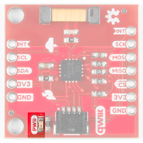
There is one red LED on the product that will turn on when power is supplied to the board. You can disconnect this LED by cutting the jumper on the underside of the product labeled LED.
Qwiic Connector or I2C Pins
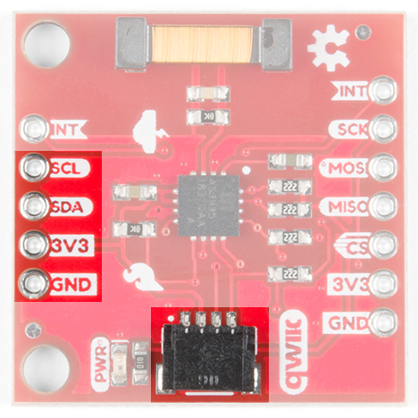
There is one Qwiic connector on the board to easily connect to the sensor via I2C. If you prefer the old school method of connecting to the I2C pins, we've also broken out those four pins on the side of the board as plated through holes.
Interrupt Pin
The interrupt pin turns high when the lightning detector has sensed an event, whether it's lightning, a disturber, or noise. Make sure to connect to this pin to check if there is an event detected.
Jumpers
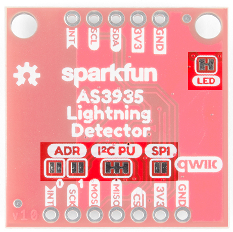
There are four jumpers on this product all on its underside.
From left to right starting at the bottom: there are two address jumpers labeled ADR that allow you to change. The default I2C address is 0x03 but it can be changed to three other options: 0x02, 0x01, 0x00. We recommend 0x03 and 0x02, but if you really know what you're doing then you can also use 0x01 or 0x00. These two addresses are reserved for special I2C commands and you can read more about I2C addressing from this article.
Next to the two address jumpers are the I2C pull-up resistor jumpers. If you have many I2C devices chained together you may have to cut these jumpers. Next to that you, have the SPI jumper that enables SPI when closed. Finally, in the upper right is the power LED disconnect jumper. If that power LED is irritating or unnecessary, then cut that jumper.
Antenna
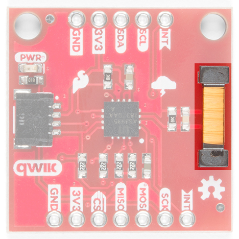
The large-ish part on the board is the board's antenna. Keep the area around the antenna free as it is what picks up lightning events. With that said, check below for some common sources of false positives and noise.
False Positives and Noise
There are a number of sources that can cause false positives but the lightning detector itself can reliably filter these out by default. If not, there are a number of settings you can configure using the lightning detector library to increase the chip's robustness to noise and false positives. However, it can help to know some potential sources of noise (from the AS3935 fact sheet) fluorescent lighting, microwave ovens, and switches. From the datasheet, it states that smartphone and smartwatch displays, and DC-DC converters can also trigger as noise. Keep in mind that you would probably have to put your lightning detector on top of your phone for it to register. I found that using the lightning detector in the office was near impossible because I'm surrounded by at least ten computers, three 3D-printers, and numerous soldering irons.
Hardware Assembly
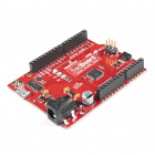
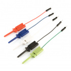
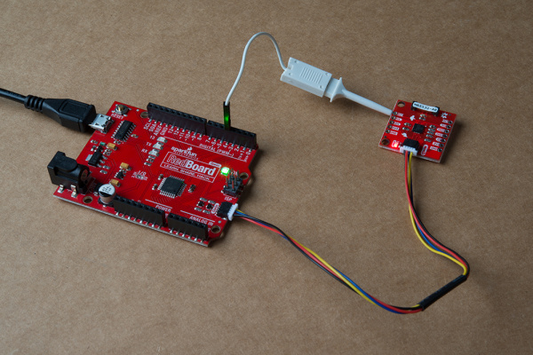
This one is very easy to put together if you have a Qwiic enabled microcontroller like the RedBoard Qwiic. Plug a Qwiic cable between the RedBoard Qwiic and the SparkFun AS3935 Lightning Detector. You will also need to solder wire between the RedBoard Qwiic's pin 4 and the Qwiic AS3935's INT pin. For quick testing, an IC hook was used. For a secure connection, we recommend soldering a header or wire between the two.
digitalRead().
Library Installation
We've provided a library for the SparkFun Lightning Detector that configures every available setting the IC offers. Some of the features include modifying the sensitivity of the antenna, whether you're inside or outside, fine tuning when the IC triggers an interrupt, or modifying the resonance frequency of the antenna. You can search the Arduino Library Manager for "SparkFun Lightning Detector", or you can click the button below to get the library and install it manually. Finally, you can also download it manually from the GitHub Repo.
Example Code
The example below will start with the basic functionality in Example1_BasicLightning.ino. Open the example up to follow along.
At the very top, we have a few defines that will help us to distinguish what sort of event the lightning detector has sensed. There are three possible "events". The first of course is lightning, but we may also get a false lightning event called a disturber, and finally we may hear noise.
language:c
#include <SPI.h>
#include <Wire.h>
#include "SparkFun_AS3935.h"

// 0x03 is default, but the address can also be 0x02, 0x01, or 0x00
// Adjust the address jumpers on the underside of the product.
#define AS3935_ADDR 0x03
#define INDOOR 0x12
#define OUTDOOR 0xE
#define LIGHTNING_INT 0x08
#define DISTURBER_INT 0x04
#define NOISE_INT 0x01

// If you using SPI, instantiate class without address:
//SparkFun_AS3935 lightning;

// If you're using I-squared-C then keep the following line. Address is set to
// default.
SparkFun_AS3935 lightning(AS3935_ADDR);

// Interrupt pin for lightning detection
const int lightningInt = 4;
int noiseFloor = 2;

// This variable holds the number representing the lightning or non-lightning
// event issued by the lightning detector.
int intVal = 0;
In the setup, we set the IC to be run inside because I'm assuming you're at your computer running this code. If you're outside change the parameter to OUTDOOR.
language:c
void setup()
{
  // When lightning is detected the interrupt pin goes HIGH.
  pinMode(lightningInt, INPUT);

  Serial.begin(115200);
  Serial.println("AS3935 Franklin Lightning Detector");

  //SPI.begin()
  Wire.begin(); // Begin Wire before lightning sensor.

  if( !lightning.begin() ) { // Initialize the sensor.
  //if( !lightning.beginSPI(9, 2000000){ // Uncomment for SPI.
    Serial.println ("Lightning Detector did not start up, freezing!");
    while(1);
  }
  else
    Serial.println("Schmow-ZoW, Lightning Detector Ready!");

  // The lightning detector defaults to an indoor setting at
  // the cost of less sensitivity, if you plan on using this outdoors
  // uncomment the following line:
  //lightning.setIndoorOutdoor(OUTDOOR);
}
...and finally the meat. Here we're just monitoring the interrupt pin. If the pin reads high, then the IC has heard some sort of event. Afterwards we're going to read the interrupt register to see what the event is, whether it's lightning, a disturber, or noise. Each of these events are printed out in the serial window at 115200 baud. The lightning event however will also print out the estimated distance to the front of the storm. Keep in mind that this is not the distance to the lightning but rather the storm.
language:c
void loop()
{
  if(digitalRead(lightningInt) == HIGH){
    // Hardware has alerted us to an event, now we read the interrupt register
    // to see exactly what it is.
    intVal = lightning.readInterruptReg();
    if(intVal == NOISE_INT){
      Serial.println("Noise.");
      //reduceNoise(); //See note below above reduceNoise function.
    }
    else if(intVal == DISTURBER_INT){
      Serial.println("Disturber.");
    }
    else if(intVal == LIGHTNING_INT){
      Serial.println("Lightning Strike Detected!");
      // Lightning! Now how far away is it? Distance estimation takes into
      // account any previously seen events in the last 15 seconds.
      byte distance = lightning.distanceToStorm();
      Serial.print("Approximately: ");
      Serial.print(distance);
      Serial.println("km away!");
    }
  }
  delay(100); //Let's not be too crazy.
}
In case you're sitting at a computer and there's a lot of RF noise in your area then you may need a way to make the lightning detection less sensitive to these events. Call this function and feed it a number lower than seven to increase it's noise threshold. Likewise, you could put this function in the noise if-statement listed above and it will increase that threshold every time a noise event occurs. This may give you an idea of which number works best for the area you're in.
language:c
void reduceNoise(){
  ++noiseFloor; // Manufacturer's default is 2 with a max of 7.
  if(noiseFloor > 7){
    Serial.println("Noise floor is at max!");
    return;
  }
  Serial.println("Increasing the event threshold.");
  lightning.setNoiseLevel(noiseFloor);
}
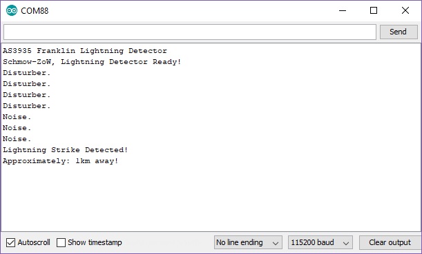
If you've heard some lightning, than you'll see the following in your Arduino serial window.
Resources and Going Further
For more on the AS3935, check out the links below:
- Schematic (PDF)
- Eagle Files (ZIP)
- Datasheet (PDF)
- GitHub
- AS3935 Lightning Detector Library
- Product Repo - Design files and more datasheets!
- SFE Product Showcase
Need some other weather sensing parts for your project? Check out some of the ones listed below.
Need some inspiration for your next project? Check out some of these related tutorials to sense your environment!
MS5803-14BA Pressure Sensor Hookup Guide
How to Make a Magic Mirror with Raspberry Pi
Artemis Global Tracker Hookup Guide
Qwiic Pressure Sensor (BMP581) Hookup Guide
Or check out this related blog post with the AS3935's SPI bus.
