Qwiic Ambient Light Sensor (VEML6030) Hookup Guide
 Elias The Sparkiest
 Introduction
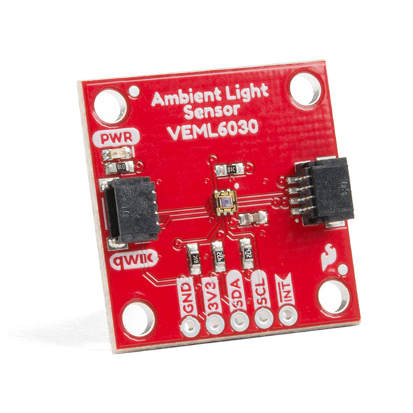
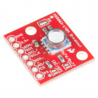
The SparkFun Ambient Light Sensor (VEML6030) is an I²C enabled ambient light sensor with high sensitivity and high accuracy. It reads ambient light in Lux and boasts a number of nice features including: the ability to set high and low thresholds for an optional interrupt, power saving features that enable single digit micro-amp current draw, and a readable range from zero to 120,000 Lux. We've also written an Arduino library that gives full access to all features and includes example code demonstrating all its' abilities. Follow along and let's learn about all its features and how to use them!
Required Materials
To follow along with the example code used in this tutorial, you will also need the following materials. You may not need everything though depending on what you have. Add it to your cart, read through the guide, and adjust the cart as necessary.
If you need different size Qwiic cables we offer a kit that contains many sizes but we also carry them individually as well:

Qwiic Cable - Breadboard Jumper (4-pin)
PRT-14425
Qwiic Cable - 100mm
PRT-14427
Qwiic Cable - 500mm
PRT-14429Suggested Reading
If you aren't familiar with the Qwiic system, we recommend reading here for an overview.
We would also recommend taking a look at the following tutorials if you aren't familiar with them.
I2C
How to Work with Jumper Pads and PCB Traces
RedBoard Qwiic Hookup Guide
Hardware Overview
Power
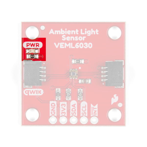
You can provide 3.3V through the Qwiic connector on the board or through the 3V3 labeled pin on the through hole header. When you correctly power the board, the on-board red power LED will turn on.

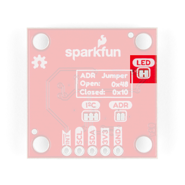
LED
There is one red LED on the product that will turn on when power is supplied to the board. You can disconnect this LED by cutting the jumper on the underside of the product labeled LED, see Jumpers below.
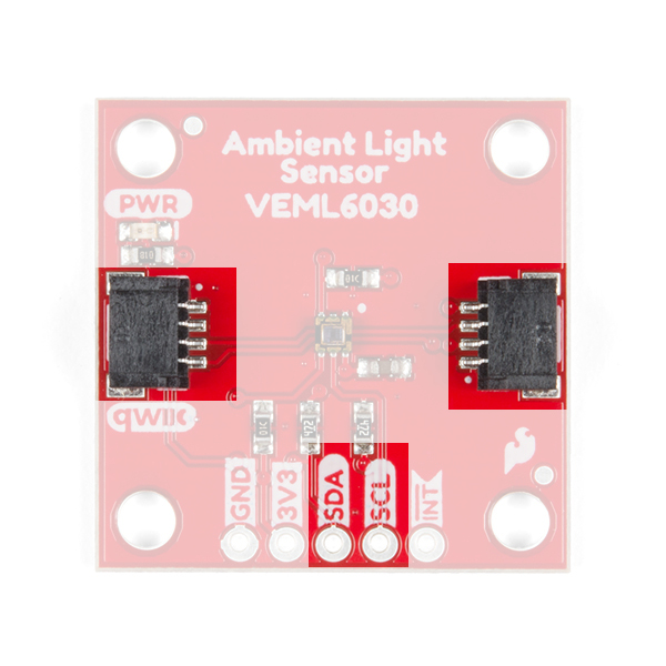
Qwiic Connector or I2C Pins
There are two Qwiic connectors on the board to easily connect to the sensor via I2C. Another option is to solder directly to the I2C plated through holes on the side of the board. We have many Qwiic sensors and Qwiic enabled micro-controllers. Check out our Qwiic Ecosystem page to get a glimpse of what else we have to offer.
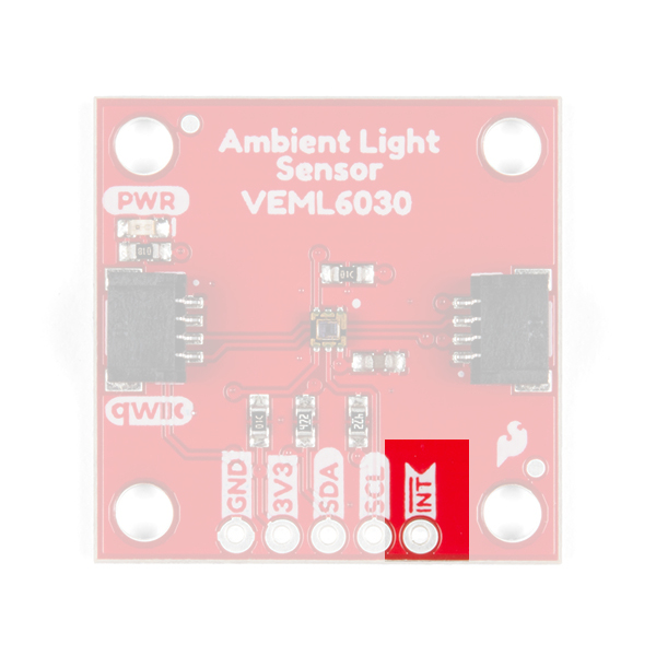
Interrupt Pin
A nice feature on the SparkFun Ambient Light sensor is its ability to set both LOW and HIGH thresholds that triggers an interrupt on the product. For example, we can know when the light in a room falls below a certain amount and conversely when the light comes back on! You don't have to settle for just the hardware interrupt though. We also have a software solution, check out the interrupt example code below.
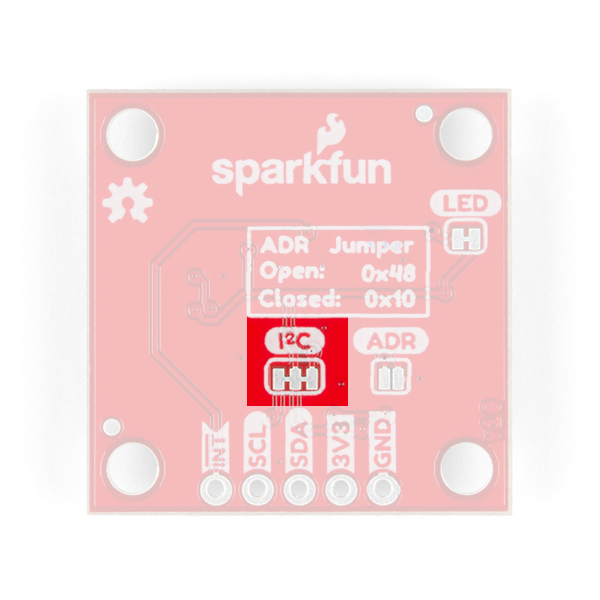
Jumpers
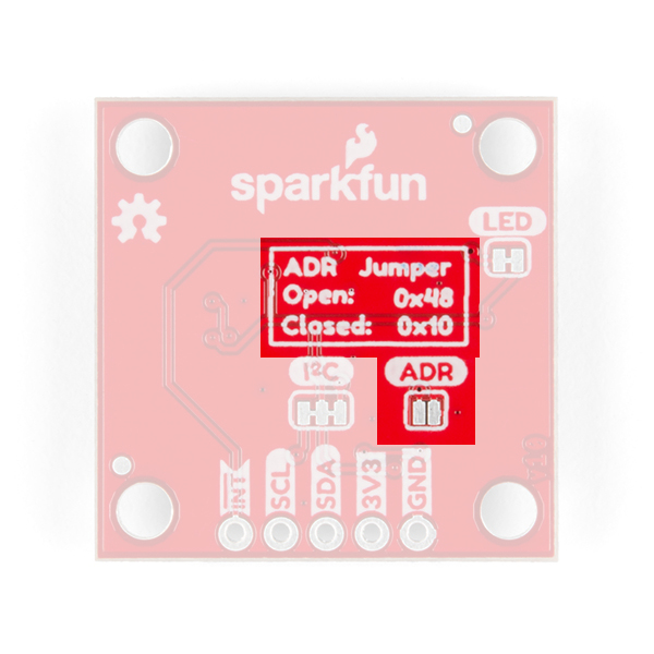
There are three jumpers on the underside of this board. Starting in the lower left is a triple jumper labeled I2C that connects pull-up resistors to the I²C data lines. If you're daisy chaining many I²C devices together than you may need to consider cutting these traces.
To the right of that is the address jumper labeled ADR that allows you to select the SparkFun Ambient Light Sensor's other I²C address: 0x10. By default your SparkFun Ambient Light Sensor is shipped with the I²C address 0x48.
Finally the jumper in the upper right is the LED jumper which can be cut to disconnect the on board power LED.
Gain and Integration Time Settings
What does gain and integration time mean? You can think of gain as an electronic mechanism to amplify a weak signal. If you're in a dark room with very little light, the sensor needs a way to amplify the weak light source to get accurate lux calculations and the gain is what give is it's oomph. Likewise, Integration time is the amount of time the sensitive photo diodes within the sensor absorb light before beginning its' Lux calculation. Both of these together are necessary for sensing in a dark room, but what if it was really bright outside?! Now there's so much light in the envinronment that you actually want to scale down the electronic's response to that saturation so you need a lower gain. And since there's so much light, the photo diodes don't need to be exposed long to get what they need to make the calculations, so a lower integration time is also needed.
The SparkFun Ambient Light Sensor can detect ranges of light in Lux from zero to 120,796! That's a gigantic range from dark to direct sun in the middle of the day. To accomplish this you have to set the Gain and Integration Time settings. This is trivial with the Arduino Library we've written and we'll walk you through it below in Example1 Ambient Light Basics. With each setting gives you a range of light that you can read. Check out the table below to see what's capable at each possible setting. Notice that slower integration and higher gain gives you a smallest range of (0->236) but the highest resolution (0.0036 lux/bit).
Maximum Light Detection Range: Lux
| Integration Time (milliseconds) | GAIN 2 | GAIN 1 | GAIN 1/4 | GAIN 1/8 |
|---|---|---|---|---|
| 800 | 236 | 472 | 1887 | 3775 |
| 400 | 472 | 944 | 3775 | 7550 |
| 200 | 944 | 1887 | 7550 | 15099 |
| 100 | 1887 | 3775 | 15099 | 30199 |
| 50 | 3775 | 7550 | 30199 | 60398 |
| 25 | 7550 | 15099 | 60398 | 120796 |
Resolution: Lux/Bit
| Integration Time (milliseconds) | GAIN 2 | GAIN 1 | GAIN 1/4 | GAIN 1/8 |
|---|---|---|---|---|
| 800 | 0.0036 | 0.0072 | 0.0288 | 0.0576 |
| 400 | 0.0072 | 0.0144 | 0.0576 | 0.1152 |
| 200 | 0.0144 | 0.0288 | 0.1152 | 0.2304 |
| 100 | 0.0288 | 0.0576 | 0.2304 | 0.4608 |
| 50 | 0.0576 | 0.1152 | 0.4608 | 0.9216 |
| 25 | 0.1152 | 0.2304 | 0.9216 | 1.8432 |
Power Save Modes
Another cool feature of the SparkFun Ambient Light Sensor is its ability to run at extremely low currents. Power save modes should be used when you're continuously reading ambient light data. For example, if you're going to gather ambient light data every second, why not use a power save mode and save battery life? There are four power save modes that can be enabled with integration times of 100ms and above. Below is a table showing the power save mode, the current draw, and it's refresh rate. Check out Example 4 in the Arduino Library to see how to set it up and use the table below as a reference.
| Integration Time | Power Save Mode | Refresh Time (milliseconds) | Current Draw (microamperes) | Resolution (lx/bit) |
|---|---|---|---|---|
| 100 | 1 | 600 | 8 | 0.0288 |
| 100 | 2 | 1100 | 5 | 0.0288 |
| 100 | 3 | 2100 | 3 | 0.0288 |
| 100 | 4 | 4100 | 2 | 0.0288 |
| 200 | 1 | 700 | 13 | 0.0144 |
| 200 | 2 | 1200 | 8 | 0.0144 |
| 200 | 3 | 2200 | 5 | 0.0144 |
| 200 | 4 | 4200 | 3 | 0.0144 |
| 400 | 1 | 900 | 20 | 0.0072 |
| 400 | 2 | 1400 | 13 | 0.0072 |
| 400 | 3 | 2400 | 8 | 0.0072 |
| 400 | 4 | 4400 | 5 | 0.0072 |
| 800 | 1 | 1300 | 28 | 0.0036 |
| 800 | 2 | 1800 | 20 | 0.0036 |
| 800 | 3 | 2800 | 13 | 0.0036 |
| 800 | 4 | 4800 | 8 | 0.0036 |
Rounding Errors?!
Later on when you read back an interrupt threshold, you may notice that the interrupt lux values are off by one in some cases. This is because of the inherent rounding error with the Ambient Light Sensor. The final Lux value is calculated by multiplying the value of the bits that represent the ambient light by a decimal number (0.2304 for example). This decimal number is rounded to a whole number (e.g. 19.97 becomes 19) because the sensor does not care about fractions of a Lux. I chose to read back the rounded number because that's the interpreted value of the ambient light sensor and what is stored in its' registers.
Hardware Hookup
This will be an easy one thanks to the Qwiic connectors. Take one end of a Qwiic cable and plug it into your RedBoard Qwiic Board and then take the other end and plug it into the SparkFun Ambient Light Sensor.

Arduino Library
If you've never connected an CH340 device to your computer before, you may need to install drivers for the USB-to-serial converter. Check out our section on How to Install CH340 Drivers for help with the installation
We've written a library to make it even easier to get started with the SparkFun Ambient Light Sensor. The library will give you the full functionality of the sensor and provides example code to get the most our of your project. You can obtain these libraries through the Arduino Library Manager by searching SparkFun Ambient Light Sensor. The second option is to download the ZIP file below from its GitHub repository to manually install.
Example 1: Ambient Light Basics
In this first example, we'll get you comfortable with gathering ambient light and setting two vital properties of the sensor's ability to read light: the gain and the integration time. These two properties determine the resolution (accuracy) of the reading and the available ranges of light that you can read! For example, a gain of 1/8 and 800ms integration time cannot read anything above 3775 Lux. This means you'll max out your sensor outdoors but would be a proper setting for dim rooms due to it's higher resolution.
At the top of the example we have three variables gain, time, and luxval. The first two hold the value for the gain and integration time settings mentioned above. Gain settings can be: 2, 1, 1/4, and 1/8; typically 1/4 gain will capture everything you need with good resolution. Possible integration times can be 800, 400, 200, 100, 50, 25 and by default the sensor is set to 100; times are in milliseconds. Check the Gain and Integration Time table above under Hardware Overview to see maximum illumination capabilities and resolution for every setting.
If you have any doubt with which settings to pick, just keep the example code's default settings: a gain of 1/4 (0.125) and an integration time of 100ms. This will give you a range of up to 15,000 Lux with a decent resolution!
language:c
#include <Wire.h>
#include "SparkFun_VEML6030_Ambient_Light_Sensor.h"

#define AL_ADDR 0x48

SparkFun_Ambient_Light light(AL_ADDR);

// Possible values: .125(1/8), .25(1/4), 1, 2
// Both .125 and .25 should be used in most cases except darker rooms.
// A gain of 2 should only be used if the sensor will be covered by a dark
// glass.
float gain = .125;

// Possible integration times in milliseconds: 800, 400, 200, 100, 50, 25
// Higher times give higher resolutions and should be used in darker light.
int time = 100
long luxVal = 0;
In the setup, we call light.begin() to check if we can communicate with the SparkFun Ambient Light Sensor. Next, we call the light.setGain() and light.setIntegTime() functions giving them the variables holding the gain and time values above. Next we'll read back those values to make sure that they were set correctly. That's it! We're now set to read some light!
language:c
void setup(){

  Wire.begin();
  Serial.begin(115200);

  if(light.begin())
    Serial.println("Ready to sense some light!");
  else
    Serial.println("Could not communicate with the sensor!");

  // Again the gain and integration times determine the resolution of the lux
  // value, and give different ranges of possible light readings. Check out
  // hoookup guide for more info.
  light.setGain(gain);
  light.setIntegTime(time);

  Serial.println("Reading settings...");
  Serial.print("Gain: ");
  float gainVal = light.readGain();
  Serial.print(gainVal, 3);
  Serial.print(" Integration Time: ");
  int timeVal = light.readIntegTime();
  Serial.println(timeVal);

}
One thing to keep in mind is that you need to set a delay() in between readings. The Integration Time is the amount of time that the sensor uses to fill its' sensitive components with light. If you set an integration time of 100ms then make sure you're delay is at least that long. A longer integration time will need a longer delay.
language:c
void loop(){

  luxVal = light.readLight();
  Serial.print("Ambient Light Reading: ");
  Serial.print(luxVal);
  Serial.println(" Lux");
  delay(1000);

}
Example 2 and 3: Ambient Light Interrupt
The SparkFun Ambient Light Sensor can issue an interrupt whenever the ambient light readings cross high or low thresholds. In this example, we'll talk about setting those thresholds and reading when those thresholds have been crossed in two different ways:
- the on-board hardware interrupt pin labeled
INT - through software monitoring
The code for both Example 2 and 3 only differ in the main loop() and these differences are highlighted under Example 2 - Hardware Interrupt and Example 3 - Software Interrupt sections below.
Again as in example one, at the top we see the gain, time and luxVal variables. The gain and integration times are vital for setting the tolerance for light and resolution of your sensor - see the Gain and Integration Time table under Hardware Overview above. The luxVal variable holds the ambient light readings further down in the code. Just below we see the interrupt settings lowThresh, highThresh and numbValues. The first two set the low and high threshold variables that will trigger the interrupt when the ambient light crosses the given values. The last variable is the number of times a value must cross a threshold to trigger an interrupt. I have the variables set to 20 Lux for the lower end, 400 Lux for the upper end, and that an interrupt must be issued after the ambient light crosses one of these thresholds once.
language:c
#include <Wire.h>
#include "SparkFun_VEML6030_Ambient_Light_Sensor.h"


// Close the address jumper on the product for addres 0x10.
#define AL_ADDR 0x48

SparkFun_Ambient_Light light(AL_ADDR);

// Possible values: .125, .25, 1, 2
// Both .125 and .25 should be used in most cases except darker rooms.
// A gain of 2 should only be used if the sensor will be covered by a dark
// glass.
float gain = .125;

// Possible integration times in milliseconds: 800, 400, 200, 100, 50, 25
// Higher times give higher resolutions and should be used in darker light.
int time = 100;
long luxVal = 0;


// Interrupt settings.
long lowThresh = 20;
long highThresh = 400;
int numbValues = 1;

// Interrupt pin
int intPin = 3;
// -- OR -- if not using interrupt pin:
int interrupt;
Again, as in the first example, we start communication with the sensor with light.begin(), set the gain (light.setGain()) and integration time settings (light.setIntegTime()), and read them back by printing them out to the serial monitor with the respective read functions. But just below we see where we set the two thresholds. First the low threshold with light.setIntLowThresh() and then the high threshold with light.setIntHighThresh(), giving these functions the values we set in the variables above. We then read those settings back to make sure that they're set correctly.
Now we set how many values will need to cross the threshold with the light.setProtect() function call and read it back. This setting is optional and defaults to one. Finally, we enable the interrupt with light.enableInt(). While the sensor knows our thresholds it does not quite know we want the interrupt to be enabled until we tell it to.
language:c
void setup(){

  Wire.begin();
  Serial.begin(115200);
  pinMode(intPin, INPUT);

  if(light.begin())
    Serial.println("Ready to sense some light!");
  else
    Serial.println("Could not communicate with the sensor!");

  // Again the gain and integration times determine the resolution of the lux
  // value, and give different ranges of possible light readings. Check out
  // hoookup guide for more info. The gain/integration time also affects
  // interrupt threshold settings so ALWAYS set gain and time first.
  light.setGain(gain);
  light.setIntegTime(time);

  Serial.println("Reading settings...");
  Serial.print("Gain: ");
  float gainVal = light.readGain();
  Serial.print(gainVal, 3);
  Serial.print(" Integration Time: ");
  int timeVal = light.readIntegTime();
  Serial.println(timeVal);

  // Set both low and high thresholds, they take values in lux.
  light.setIntLowThresh(lowThresh);
  light.setIntHighThresh(highThresh);
  // Let's check that they were set correctly.
  // There are some rounding issues inherently in the IC's design so your lux
  // may be one off.
  Serial.print("Low Threshold: ");
  long lowVal = light.readLowThresh();
  Serial.print(lowVal);
  Serial.print(" High Threshold: ");
  long highVal = light.readHighThresh();
  Serial.println(highVal);

  // This setting modifies the number of times a value has to fall below or
  // above the threshold before the interrupt fires! Values include 1, 2, 4 and
  // 8.
  light.setProtect(numbValues);
  Serial.print("Number of values that must fall below/above threshold before interrupt occurrs: ");
  int protectVal = light.readProtect();
  Serial.println(protectVal);

  // Now we enable the interrupt, now that he thresholds are set.
  light.enableInt();
  Serial.print("Is interrupt enabled: ");
  int enabInt = light.readIntSetting();
  if( enabInt == 1 )
    Serial.println("Yes");
  else
    Serial.println("No");

  Serial.println("-------------------------------------------------");

  // Give some time to read our settings on startup.
  delay(3000);
}
Example 2: Hardware Interrupt
Now let's read some light! Since we're just using a hardware interrupt we have a pin attached to PIN 3. When the ambient light reading passes either threshold the pin will go LOW. When an interrupt fires we check to see which threshold was crossed and print it out in the serial monitor.
language:c
void loop(){

  luxVal = light.readLight();
  Serial.print("Ambient Light Reading: ");
  Serial.print(luxVal);
  Serial.println(" Lux");

  if (digitalRead(intPin) == LOW){
    int intVal = light.readInterrupt();
    if (intVal == 1)
      Serial.println("High threshold crossed!");
    else if (intVal == 2){
      Serial.println("Low threshold crossed!");
    }
  }

  delay(200);
Example 3: Software Interrupt
If you're committed to keeping this Qwiic then we can look for an interrupt by monitoring the Ambient Light Sensor directly rather than through a digital pin. In the code we'll use the light.readInterrupt() function call directly to see if there's been an interrupt issued. That's it!
language:c
void loop(){

  luxVal = light.readLight();
  Serial.print("Ambient Light Reading: ");
  Serial.print(luxVal);
  Serial.println(" Lux");

  interrupt = light.readInterrupt();
  if (interrupt == 1)
    Serial.println("High threshold crossed!");
  else if (interrupt == 2){
    Serial.println("Low threshold crossed!");

  delay(200);

}
Example 4 - Power Save Mode
I won't break down this example code because you have all the necessary tools to get you started with the Ambient Light Sensor. However, if you plan on continuously reading ambient light data then give this sketch a try. It'll show you how to put the board into power save mode, which will save you battery life while still getting ambient light data. Check the Power Save Mode section under Hardware Overview as a reference when looking at the sketch.
Resources and Going Further
For more on the AS3935, check out the links below:
- Schematic (PDF)
- Eagle Files (ZIP)
- Datasheet (PDF)
- GitHub
- SparkFun Ambient Light Sensor Arduino LIbrary
- Product Repo - Design files and more datasheets!
- SFE Product Showcase
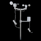
Need some other weather sensing parts for your project? Check out some of the ones listed below.
Need some inspiration for your next project? Check out some of these related tutorials to sense your environment!