Spectral Triad (AS7265x) Hookup Guide
 Nate
Nate Introduction
The SparkFun Triad Spectroscopy Sensor is a powerful optical inspection sensor. Three AS7265x sensors are combined alongside a visible, UV, and IR LEDs to illuminate and test various surfaces for light spectroscopy.
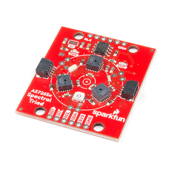
AMS has combined the power of three sensors to cover the measurement of light from 410nm to 940nm in 18 individual bands.

What Can You Do with Light Spectroscopy?
It’s an amazing field of study, and the SparkFun Triad brings what used to be prohibitively expensive equipment to the desktop. The AS7265x should not be confused with highly complex mass spectrometers, but the sensor array does give the user the ability to measure and characterize how different materials absorb and reflect 18 different frequencies of light.
Required Materials
To follow along with this hookup guide, you will need one of the following Qwiic shields with an Arduino. You may not need everything though depending on what you have. Add it to your cart, read through the guide, and adjust the cart as necessary.


You will also need a Qwiic cable to connect the shield to your AS726X, choose a length that suits your needs.

Qwiic Cable - 50mm
PRT-14426
Qwiic Cable - 100mm
PRT-14427
Qwiic Cable - 200mm
PRT-14428
Qwiic Cable - 500mm
PRT-14429Tools
Depending on your setup, you may need a soldering iron, solder, and general soldering accessories.


Weller WLC100 Soldering Station
TOL-14228Suggested Reading
If you aren't familiar with the Qwiic system, we recommend reading here for an overview.
| Qwiic Connect System |
We also recommend checking out these tutorials before continuing.
Light
I2C
Qwiic Shield for Arduino & Photon Hookup Guide
Hardware Overview
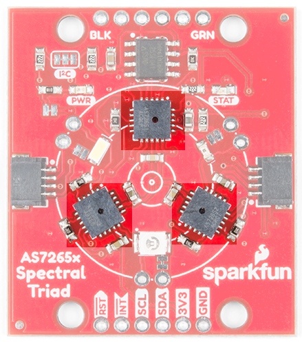
Sensors
The Triad is made up of three sensors; AS72651 (UV), AS72652 (VIS), and AS72653 (NIR). The AS72651 communicates with the x2 and x3 sensors over a dedicated I2C bus (the AS72651 is the master, the AS72652 and AS72653 are slaves). The AS72651 combines its sensor data with the data from the x2 and x3 sensors and exposes the datums to the user as a single array of registers. The SparkFun AS7265x Spectral Library makes it seamless to read any of the 18 frequencies of sensing.
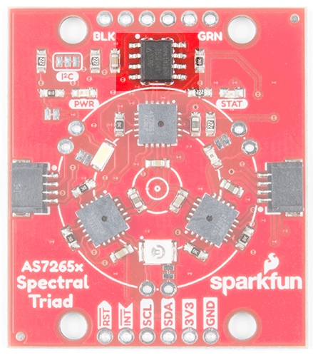
EEPROM
These sensors from AMS are interesting in that they ship without firmware. The firmware to drive the system is loaded onto a 4Mbit EEPROM that is read by the AS72651 at power on.
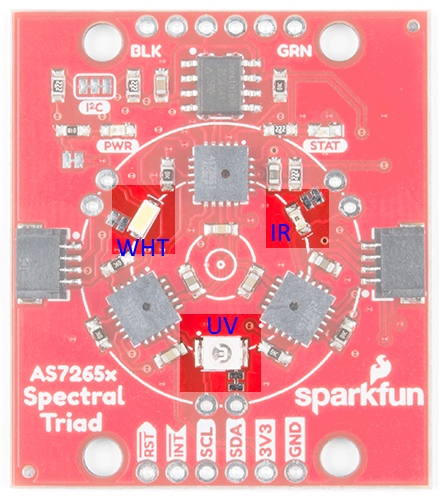
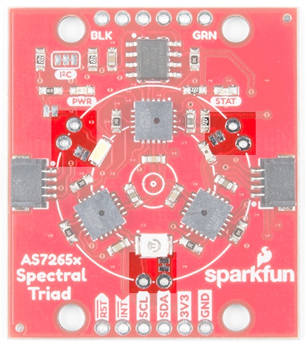
LEDs / Bulbs
The Triad contains a 5700k white LED, a 405nm UV LED, and a 875nm IR LED mounted alongside the sensors. These LEDs were chosen to illuminate the target with the largest swath of visible and invisible light. The LEDs are individually enabled with software configurable drive current.
The board also has multiple ways for you to illuminate the object that you are trying to measure for a more accurate spectroscopy reading. If you aren’t satisfied with the on-board, LEDs you can grab your own through hole incandescent bulbs. While you should find a bulb rated for 3.3V, a bulb rated for higher voltage, like 5V, will still work, but will not run as bright as it normally would with 5V. We’ve found that Mouser is a good place to look for these. If you are going to go that route and use your own bulb, be sure to disable the onboard LED by removing cutting the jumper to any 'bulb' footprint that is used. Cut the jumper next to each bulb footprint to disconnect the LED from the controller IC and solder in a bulb. We use the word ‘bulb’ to indicate any DC device (limited to 100mA max) but this signal pin could also be used to activate a larger MOSFET or control device to activate a much larger current device.
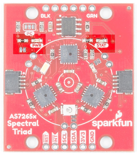
In addition to the illumination LEDs, there is a power LED and a status LED. The blue status LED indicates various states of the AS72651 sensor and can be disabled through the SparkFun library. The red power LED is provided to indicate the board is properly energized. If the red light is interfering with readings it can be disabled by cutting the neighboring jumper.
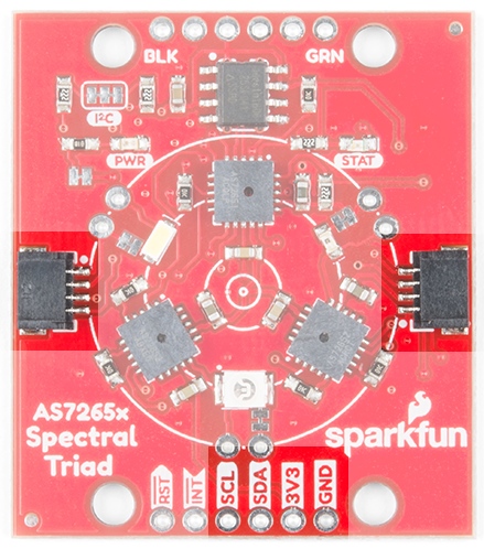
I2C / Qwiic Interface
The Qwiic connectors provide a quick and easy way to connect the Triad over I2C. Alternatively, you can solder to the four pins: GND/3.3V/SDA/SCL. The sensors are 3.3V compatible so don’t use with a 5V Arduino Uno without proper conversion (use the Qwiic shield instead!). If you're using a 3.3V development platform that doesn't have a Qwiic connector, consider using the Qwiic Breadboard Cable.
Serial UART Interface
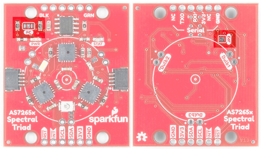
A serial interface is also available for those users who prefer using AT commands. Please refer to the AS7265x datasheet for a full list of commands. To enable the serial interface (and disable the I2C interface) you must modify two jumpers:
- The I2C jumper on the front of the board must be opened to remove the pull-up resistors from the TX and RX lines.
- The JP2 on the rear of the board must be closed with a solder jumper.
Next, solder in a 6-pin right angle male header to the serial port.
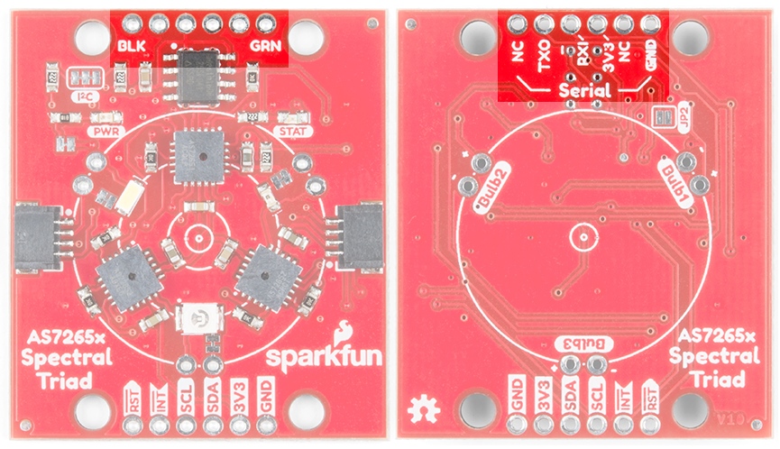
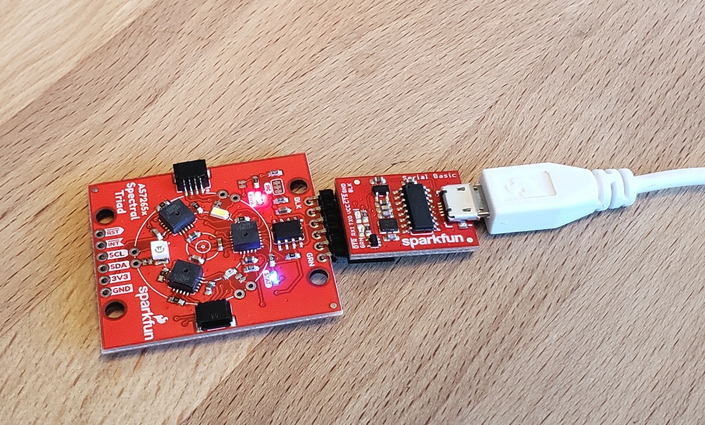
The SparkFun Serial Basic connects directly to the Triad. The Serial Basic is set to 3.3V by default but if you’re using a different board, be sure it provides 3.3V on VCC and uses 3.3V logic signals.
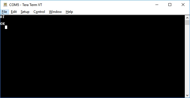
The serial interface operates at 115200. To test the connection, open TeraTerm or your favorite terminal and connect to the Serial Basic. Send the command AT and look for an OK response. You’re all set! Check the AS7265x datasheet for a full list of AT commands.
AS7265x Arduino Library Overview
We’ve written an Arduino library to make reading the Triad a breeze. The easiest way to install the library is by searching SparkFun Spectral Triad within the Arduino library manager. You can also manually install the AS7265x library by downloading a zip:
Example 1 provided with the library demonstrates how to read all 18 channels. The higher examples demonstrate all the features available through the SparkFun library on the Spectral Triad:
- Example 1 - Basic readings of all 18 channels
- Example 2 - Controlling the onboard LEDs
- Example 3 - Changing the many settings on the AS7652x
- Example 4 - Output the raw sensor readings without calibration adjustment
- Example 5 - Setting the sensor up for maximum read speed
- Example 6 - Reading the temperatures of the three ICs
- Example 7 - Reading the various hardware and firmware versions
Below are the various functions that can be called from the library. Most of these functions are demonstrated in the examples so we recommend you go through each example first.
boolean begin(TwoWire &wirePort = Wire);-- Inits the sensor with default settings. Optional pass of wire port.boolean isConnected();-- Returns true if the sensor is detected on the I2C busboolean dataAvailable();-- Returns true when data is availableuint8_t getTemperature(uint8_t deviceNumber = 0);-- Get temp in C of the master ICfloat getTemperatureAverage();-- Get average of all three ICsvoid takeMeasurements();-- Tell sensor to take one-shot measurementvoid takeMeasurementsWithBulb();-- Take one-shot measurement with all three LEDs illuminatedfloat getCalibratedA();togetCalibratedW();-- Returns the various calibration datauint16_t getA();togetW();-- Get the various raw readingsvoid enableIndicator();-- Enable the blue status LEDvoid disableIndicator();-- Disable the status LED. Handy when taking snesitive readingsvoid enableBulb(uint8_t device);-- Turn on a given LED. 0 = White, 1 = IR, 2 = UVvoid disableBulb(uint8_t device);-- Turn off a given LEDvoid setGain(uint8_t gain);-- 1 to 64xvoid setMeasurementMode(uint8_t mode);-- 4 channel, other 4 channel, 6 chan, or 6 chan one shotvoid setIntegrationCycles(uint8_t cycleValue);-- 2.78ms to 711msvoid setBulbCurrent(uint8_t current, uint8_t device);-- 12.5mA to 100mAvoid setIndicatorCurrent(uint8_t current);-- 1 to 8mAvoid enableInterrupt();-- Enable the interrupt pin (active low)void disableInterrupt();void softReset();-- Reset the device via softwareuint8_t getDeviceType();-- Should return 0x41uint8_t getHardwareVersion();-- Should return 0x40uint8_t getMajorFirmwareVersion();-- Returns the current firmware version, currently 0x0Cuint8_t getPatchFirmwareVersion();uint8_t getBuildFirmwareVersion();
Example: Taking A Banana Reading
Let's get the Triad hooked up over Qwiic and begin illuminating a target to take some readings. Using a BlackBoard and a Qwiic Cable we're able to attach to the Triad quickly without soldering. Let's open and use Example 2 from the library so that the Triad will take all 18 readings while illuminating the target.
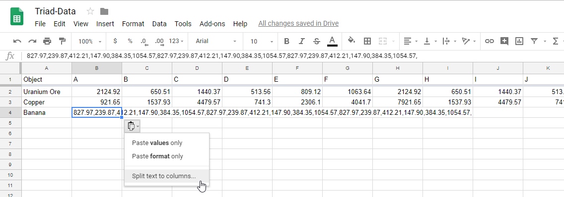
Once you have a series of readings, plug them into your favorite graph utility. For our purposes, we like to use Google spreadsheets. You can paste the comma delimited output from the sketch directly into a sheet. Once there, drop the small menu down and select Split text to columns.
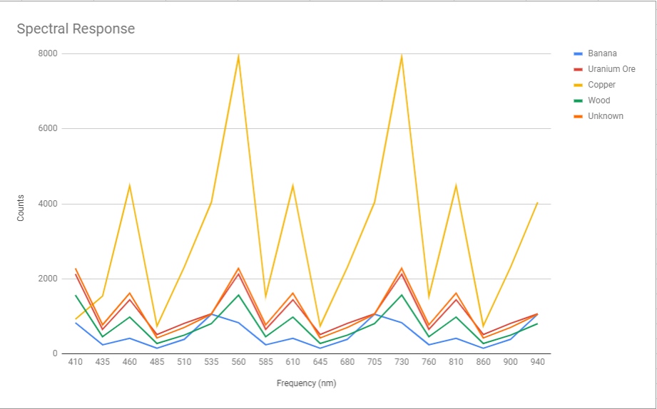
You can access our data here. The graph of the 18 frequencies is pretty neat!

Now that we have a baseline we can take a reading from an unknown thing (in this case, Uranium ore we had sitting around used for testing the Pocket Geiger Counter). Note that the distance to your sample will cause the amplitude of the readings to increase or decrease. We took our readings holding the Triad about 1 inch away from the surface of the target sample but a 3D printed shroud would remove background illumination and remove read distance variations.
As you can see the unknown sample follows closely to the Uranium Ore signature.
Science! The Triad is a fantastic tool that will have you looking around your house for interesting things to measure.
Resources and Going Further
Now that you've successfully got your Spectral Triad up and running, it's time to incorporate it into your own project!
For more information, check out the resources below:
- SparkFun Triad Schematic (PDF)
- Eagle Files (ZIP)
- Datasheets
- Qwiic System Information
- GitHub
- SparkFun Qwiic Spectral Sensor Repo -- Eagle files, datasheets for LEDs, design considerations, etc.
- SparkFun AS7265x Arduino Library Repo
- SFE Product Showcase
Need some inspiration for your next project? Check out some of these related tutorials: