MicroMod RP2040 Processor Board Hookup Guide
 bboyho
 Introduction
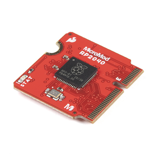
The MicroMod RP2040 Processor Board is a low-cost, high-performance board with flexible digital interfaces featuring the Raspberry Pi Foundation's RP2040 microcontroller. The board takes advantage of the MicroMod M.2 connector to easily swap out processor boards on carrier boards.
SparkFun MicroMod RP2040 Processor
DEV-17720Required Materials
To follow along with this tutorial, you will need the following materials. You may not need everything though depending on what you have. Add it to your cart, read through the guide, and adjust the cart as necessary.

SparkFun MicroMod RP2040 Processor
DEV-17720Suggested Reading
If you aren't familiar with the MicroMod ecosystem, we recommend reading here for an overview. We recommend reading here for an overview if you decide to take advantage of the Qwiic connector.
 |
|
| MicroMod Ecosystem | Qwiic Connect System |
If you aren’t familiar with the following concepts, we also recommend checking out these tutorials before continuing.
Serial Communication
Serial Peripheral Interface (SPI)
Pulse Width Modulation
Logic Levels
I2C
Analog vs. Digital
Getting Started with MicroMod
Hardware Overview
M.2 Connector
All of our MicroMod Processor Boards come equipped with the M.2 MicroMod Connector, which leverages the M.2 standard and specification to allow you to install your MicroMod Processor Board on your choice of carrier board. Most of the pins use a common pinout to ensure cross platform compatibility.
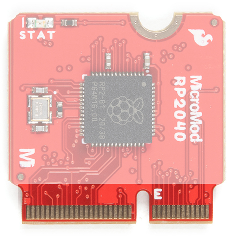
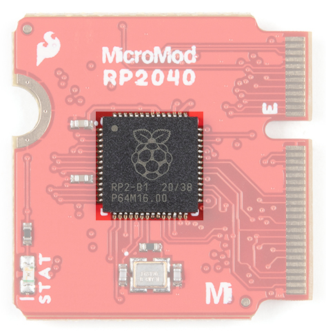
RP2040 Processor
The brains of the processor board is the Raspberry Pi Foundation's RP2040 ARM Cortex M0+ processor. An external 12MHz crystal is used as the clock for the RP2040. The RP2040 should be powered with 3.3V from a carrier board's M.2 connector. The logic levels for the I/O pins are 3.3V.
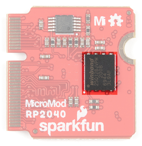
Flash Memory
On the back of the board is the W25Q128JVPIM, which adds 128Mb (16MB) of flash memory externally.
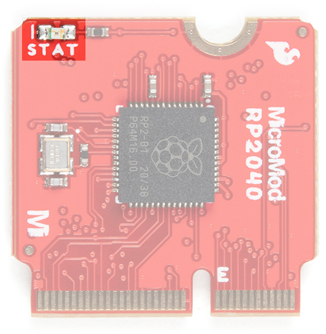
LED
A STAT LED is added to the top side of the board. This is useful debugging or as a status indicator. This is connected to GPIO25.
MicroMod RP2040 Processor Pin Functionality
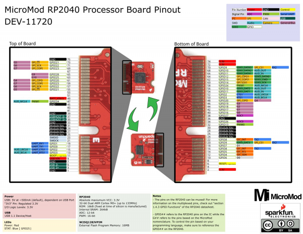
The complete pin map can be found in the table below or you can refer to the schematic.
Depending on your window size, you may need to use the horizontal scroll bar at the bottom of the table to view the additional pin functions. Note that the M.2 connector pins on opposing sides are offset from each other as indicated by the bottom pins where it says (Not Connected)*. There is no connection to pins that have a "-".
| AUDIO | UART | GPIO/BUS | I2C | SDIO | SPI | Dedicated |
| Alternate Function |
Primary Function |
RP2040 GPIO Pin | Bottom Pin |
Top Pin |
RP2040 GPIO Pin |
Primary Function |
Alternate Function |
||
|---|---|---|---|---|---|---|---|---|---|
| (Not Connected)* | 75 | GND | |||||||
| 3.3V | 74 | 73 | GPIO21 | ||||||
| 3.3V | 72 | 71 | GPIO22 | ||||||
| SPI_CS1 | SDIO_DATA3 | GPIO9 | 70 | 69 | GPIO23 | ||||
| AUD_OUT | SDIO_DATA2 | GPIO10 | 68 | 67 | - | ||||
| AUD_IN | SDIO_DATA1 | GPIO11 | 66 | 65 | GPIO28 | G9 | |||
| SDIO_DATA0 | SPI_CIPO1 | GPIO12 | 64 | 63 | GPIO25 | G10 | |||
| SDIO_CMD | SPI_COPI1 | GPIO15 | 62 | 61 | GPIO20 | SPI_CIPO | G4 | ||
| SDIO_SCK | SPI_SCK1 | GPIO14 | 60 | 59 | GPIO23 | SPI_COPI | G7 | ||
| AUD_MCLK | PWM1 | GPIO24 | 58 | 57 | GPIO22 | SPI_SCK | G6 | ||
| AUD_OUT | SDIO_DAT2 | GPIO10 | 56 | 55 | GPIO21 | SPI_CS | G5 | ||
| AUD_IN | SDIO_DAT1 | GPIO11 | 54 | 53 | - | ||||
| AUD_LRCLK | CTS1 | GPIO2 | 52 | 51 | - | ||||
| AUD_BCLK | UART_RTS1 | GPIO3 | 50 | 49 | BATT_VIN | ||||
| G4 | SPI_CIPO | GPIO20 | 48 | 47 | GPIO24 | PWM1 | AUD_MCLK | ||
| G3 | GPIO19 | 46 | 45 | GND | |||||
| G2 | GPIO18 | 44 | 43 | - | |||||
| G1 | GPIO17 | 42 | 41 | - | |||||
| G0 | GPIO16 | 40 | 39 | GND | |||||
| A1 | GPIO27 | 38 | 37 | USBHOST_D- | |||||
| GND | 36 | 35 | USBHOST_D+ | ||||||
| A0 | GPIO26 | 34 | 33 | GND | |||||
| PWM0 | GPIO13 | 32 | 31 | Module Key | |||||
| Module Key | 30 | 29 | Module Key | ||||||
| Module Key | 28 | 27 | Module Key | ||||||
| Module Key | 26 | 25 | Module Key | ||||||
| Module Key | 24 | 23 | SWDIO | ||||||
| I2C_INT | UART_TX2 | GPIO8 | 22 | 21 | SWDCK | ||||
| SPI_CS1 | SDIO_DAT3 | UART_RX2 | GPIO9 | 20 | 19 | GPIO1 | UART_RX1 | ||
| D1 | GPIO7 | 18 | 17 | GPIO0 | UART_TX1 | ||||
| TX2 | I2C_INT | GPIO8 | 16 | 15 | GPIO2 | UART_CTS1 | AUD_LRCLK | ||
| I2C_SCL | GPIO5 | 14 | 13 | GPIO3 | UART_RTS1 | AUD_BCLK | |||
| I2C_SDA | GPIO4 | 12 | 11 | BOOT | |||||
| D0 | GPIO6 | 10 | 9 | USB_VIN | |||||
| - | 8 | 7 | GND | ||||||
| RESET | 6 | 5 | USB_D- | ||||||
| - | 4 | 3 | USB_D+ | ||||||
| 3.3V_IN | 2 | 1 | GND | ||||||
| Function | Bottom Pin |
Top Pin |
Function | ||||||
|---|---|---|---|---|---|---|---|---|---|
| (Not Connected)* | 75 | GND | |||||||
| 3.3V | 74 | 73 | G5 / BUS5 | ||||||
| RTC_3V_BATT | 72 | 71 | G6 / BUS6 | ||||||
| SPI_CS1 | SDIO_DATA3 | 70 | 69 | G7 / BUS7 | |||||
| SDIO_DATA2 | 68 | 67 | G8 | ||||||
| SDIO_DATA1 | 66 | 65 | G9 | ADC_D- | CAM_HSYNC | ||||
| SPI_CIPO1 | SDIO_DATA0 | 64 | 63 | G10 | ADC_D+ | CAM_VSYNC | |||
| SPI COPI1 | SDIO_CMD | 62 | 61 | SPI_CIPO | |||||
| SPI SCK1 | SDIO_SCK | 60 | 59 | SPI_COPI | LED_DAT | ||||
| AUD_MCLK | 58 | 57 | SPI_SCK | LED_CLK | |||||
| CAM_MCLK | PCM_OUT | I2S_OUT | AUD_OUT | 56 | 55 | SPI_CS | |||
| CAM_PCLK | PCM_IN | I2S_IN | AUD_IN | 54 | 53 | I2C_SCL1 | |||
| PDM_DATA | PCM_SYNC | I2S_WS | AUD_LRCLK | 52 | 51 | I2C_SDA1 | |||
| PDM_CLK | PCM_CLK | I2S_SCK | AUD_BCLK | 50 | 49 | BATT_VIN / 3 (I - ADC) (0 to 3.3V) | |||
| G4 / BUS4 | 48 | 47 | PWM1 | ||||||
| G3 / BUS3 | 46 | 45 | GND | ||||||
| G2 / BUS2 | 44 | 43 | CAN_TX | ||||||
| G1 / BUS1 | 42 | 41 | CAN_RX | ||||||
| G0 / BUS0 | 40 | 39 | GND | ||||||
| A1 | 38 | 37 | USBHOST_D- | ||||||
| GND | 36 | 35 | USBHOST_D+ | ||||||
| A0 | 34 | 33 | GND | ||||||
| PWM0 | 32 | 31 | Module Key | ||||||
| Module Key | 30 | 29 | Module Key | ||||||
| Module Key | 28 | 27 | Module Key | ||||||
| Module Key | 26 | 25 | Module Key | ||||||
| Module Key | 24 | 23 | SWDIO | ||||||
| UART_TX2 | 22 | 21 | SWDCK | ||||||
| UART_RX2 | 20 | 19 | UART_RX1 | ||||||
| CAM_TRIG | D1 | 18 | 17 | UART_TX1 | |||||
| I2C_INT | 16 | 15 | UART_CTS1 | ||||||
| I2C_SCL | 14 | 13 | UART_RTS1 | ||||||
| I2C_SDA | 12 | 11 | BOOT (Open Drain) | ||||||
| D0 | 10 | 9 | USB_VIN | ||||||
| SWO | G11 | 8 | 7 | GND | |||||
| RESET# (Open Drain) | 6 | 5 | USB_D- | ||||||
| 3.3V_EN | 4 | 3 | USB_D+ | ||||||
| 3.3V | 2 | 1 | GND | ||||||
| Signal Group | Signal | I/O | Description | Voltage | Power | 3.3V | I | 3.3V Source | 3.3V |
|---|---|---|---|---|
| GND | Return current path | 0V | ||
| USB_VIN | I | USB VIN compliant to USB 2.0 specification. Connect to pins on processor board that require 5V for USB functionality | 4.8-5.2V | |
| RTC_3V_BATT | I | 3V provided by external coin cell or mini battery. Max draw=100μA. Connect to pins maintaining an RTC during power loss. Can be left NC. | 3V | |
| 3.3V_EN | O | Controls the carrier board's main voltage regulator. Voltage above 1V will enable 3.3V power path. | 3.3V | |
| BATT_VIN/3 | I | Carrier board raw voltage over 3. 1/3 resistor divider is implemented on carrier board. Amplify the analog signal as needed for full 0-3.3V range | 3.3V | |
| Reset | Reset | I | Input to processor. Open drain with pullup on processor board. Pulling low resets processor. | 3.3V |
| Boot | I | Input to processor. Open drain with pullup on processor board. Pulling low puts processor into special boot mode. Can be left NC. | 3.3V | |
| USB | USB_D± | I/O | USB Data ±. Differential serial data interface compliant to USB 2.0 specification. If UART is required for programming, USB± must be routed to a USB-to-serial conversion IC on the processor board. | |
| USB Host | USBHOST_D± | I/O | For processors that support USB Host Mode. USB Data±. Differential serial data interface compliant to USB 2.0 specification. Can be left NC. | |
| CAN | CAN_RX | I | CAN Bus receive data. | 3.3V |
| CAN_TX | O | CAN Bus transmit data. | 3.3V | |
| UART | UART_RX1 | I | UART receive data. | 3.3V |
| UART_TX1 | O | UART transmit data. | 3.3V | |
| UART_RTS1 | O | UART ready to send. | 3.3V | |
| UART_CTS1 | I | UART clear to send. | 3.3V | |
| UART_RX2 | I | 2nd UART receive data. | 3.3V | |
| UART_TX2 | O | 2nd UART transmit data. | 3.3V | |
| I2C | I2C_SCL | I/O | I2C clock. Open drain with pullup on carrier board. | 3.3V |
| I2C_SDA | I/O | I2C data. Open drain with pullup on carrier board | 3.3V | |
| I2C_INT# | I | Interrupt notification from carrier board to processor. Open drain with pullup on carrier board. Active LOW | 3.3V | |
| I2C_SCL1 | I/O | 2nd I2C clock. Open drain with pullup on carrier board. | 3.3V | |
| I2C_SDA1 | I/O | 2nd I2C data. Open drain with pullup on carrier board. | 3.3V | |
| SPI | SPI_COPI | O | SPI Controller Output/Peripheral Input. | 3.3V |
| SPI_CIPO | I | SPI Controller Input/Peripheral Output. | 3.3V | |
| SPI_SCK | O | SPI Clock. | 3.3V | |
| SPI_CS# | O | SPI Chip Select. Active LOW. Can be routed to GPIO if hardware CS is unused. | 3.3V | |
| SPI/SDIO | SPI_SCK1/SDIO_CLK | O | 2nd SPI Clock. Secondary use is SDIO Clock. | 3.3V |
| SPI_COPI1/SDIO_CMD | I/O | 2nd SPI Controller Output/Peripheral Input. Secondary use is SDIO command interface. | 3.3V | |
| SPI_CIPO1/SDIO_DATA0 | I/O | 2nd SPI Peripheral Input/Controller Output. Secondary use is SDIO data exchange bit 0. | 3.3V | |
| SDIO_DATA1 | I/O | SDIO data exchange bit 1. | 3.3V | |
| SDIO_DATA2 | I/O | SDIO data exchange bit 2. | 3.3V | |
| SPI_CS1/SDIO_DATA3 | I/O | 2nd SPI Chip Select. Secondary use is SDIO data exchange bit 3. | 3.3V | |
| Audio | AUD_MCLK | O | Audio master clock. | 3.3V |
| AUD_OUT/PCM_OUT/I2S_OUT/CAM_MCLK | O | Audio data output. PCM synchronous data output. I2S serial data out. Camera master clock. | 3.3V | |
| AUD_IN/PCM_IN/I2S_IN/CAM_PCLK | I | Audio data input. PCM syncrhonous data input. I2S serial data in. Camera periphperal clock. | 3.3V | |
| AUD_LRCLK/PCM_SYNC/I2S_WS/PDM_DATA | I/O | Audio left/right clock. PCM syncrhonous data SYNC. I2S word select. PDM data. | 3.3V | |
| AUD_BCLK/PCM_CLK/I2S_CLK/PDM_CLK | O | Audio bit clock. PCM clock. I2S continuous serial clock. PDM clock. | 3.3V | |
| SWD | SWDIO | I/O | Serial Wire Debug I/O. Connect if processor board supports SWD. Can be left NC. | 3.3V |
| SWDCK | I | Serial Wire Debug clock. Connect if processor board supports SWD. Can be left NC. | 3.3V | |
| ADC | A0 | I | Analog to digital converter 0. Amplify the analog signal as needed to enable full 0-3.3V range. | 3.3V |
| A1 | I | Analog to digital converter 1. Amplify the analog signal as needed to enable full 0-3.3V range. | 3.3V | |
| PWM | PWM0 | O | Pulse width modulated output 0. | 3.3V |
| PWM1 | O | Pulse width modulated output 1. | 3.3V | |
| Digital | D0 | I/O | General digital input/output pin. | 3.3V |
| D1/CAM_TRIG | I/O | General digital input/output pin. Camera trigger. | 3.3V | |
| General/Bus | G0/BUS0 | I/O | General purpose pins. Any unused processor pins should be assigned to Gx with ADC + PWM capable pins given priority (0, 1, 2, etc.) positions. The intent is to guarantee PWM, ADC and Digital Pin functionality on respective ADC/PWM/Digital pins. Gx pins do not guarantee ADC/PWM function. Alternative use is pins can support a fast read/write 8-bit or 4-bit wide bus. | 3.3V |
| G1/BUS1 | I/O | 3.3V | ||
| G2/BUS2 | I/O | 3.3V | ||
| G3/BUS3 | I/O | 3.3V | ||
| G4/BUS4 | I/O | 3.3V | ||
| G5/BUS5 | I/O | 3.3V | ||
| G6/BUS6 | I/O | 3.3V | ||
| G7/BUS7 | I/O | 3.3V | ||
| G8 | I/O | General purpose pin | 3.3V | |
| G9/ADC_D-/CAM_HSYNC | I/O | Differential ADC input if available. Camera horizontal sync. | 3.3V | |
| G10/ADC_D+/CAM_VSYNC | I/O | Differential ADC input if available. Camera vertical sync. | 3.3V | |
| G11/SWO | I/O | General purpose pin. Serial Wire Output | 3.3V |
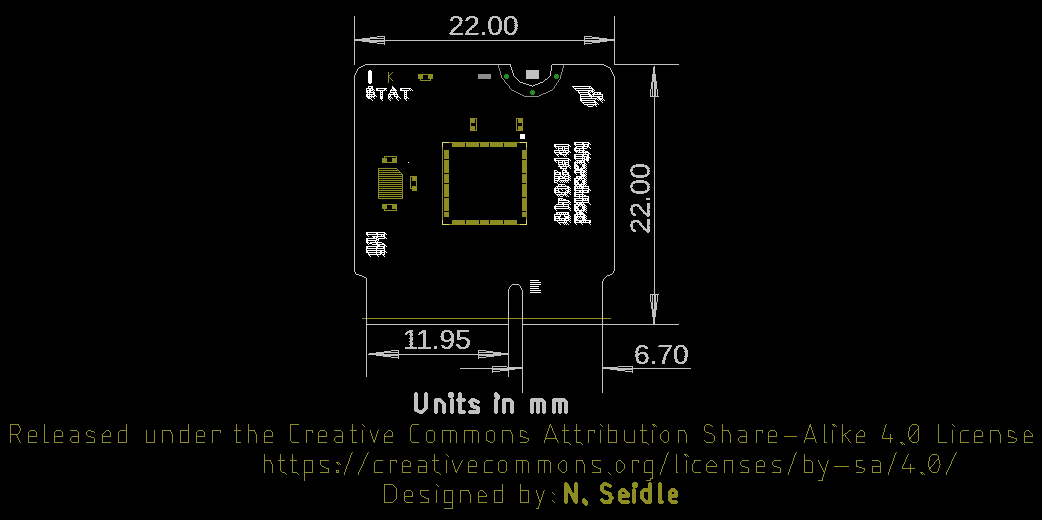
Board Dimensions
The board takes advantage of the standard MicroMod form factor.
Hardware Assembly
If you have not already, make sure to check out the Getting Started with MicroMod: Hardware Hookup for information on inserting your Processor Board into your Carrier Board.
Getting Started with MicroMod
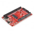
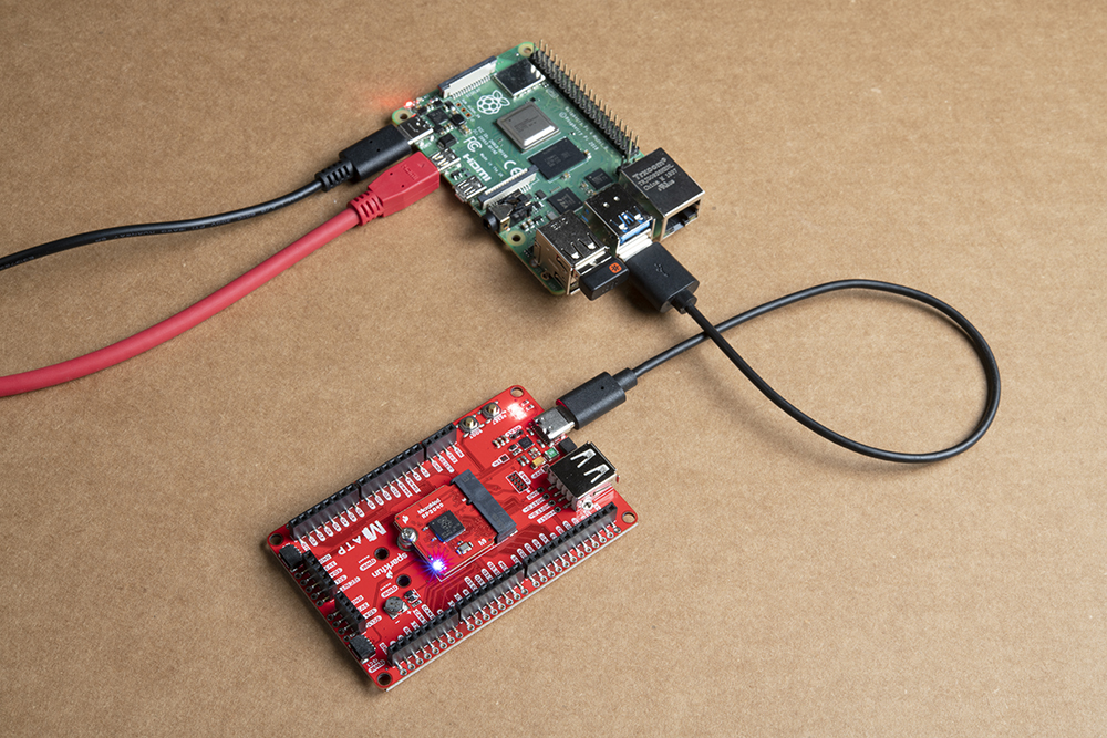
For simplicity, we'll be using the MicroMod ATP Carrier Board to program the board. At a minimum, your setup may look like the image below with the MicroMod RP2040 Processor Board.
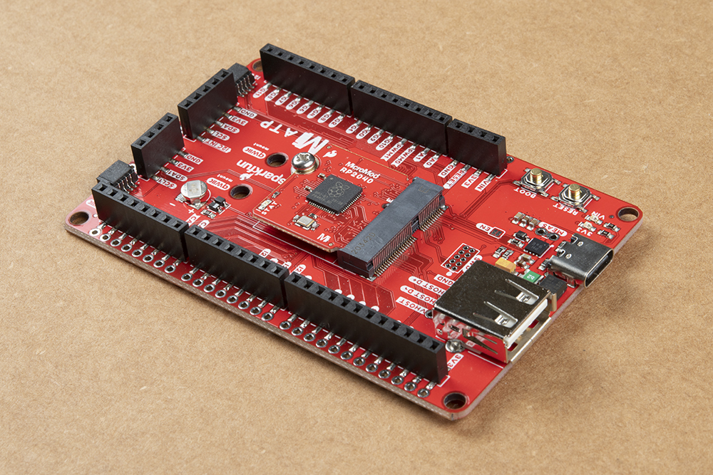
To program, you'll need a computer and a USB-C cable inserted into the MicroMod ATP Carrier Board. In this tutorial, we will use a Raspberry Pi.

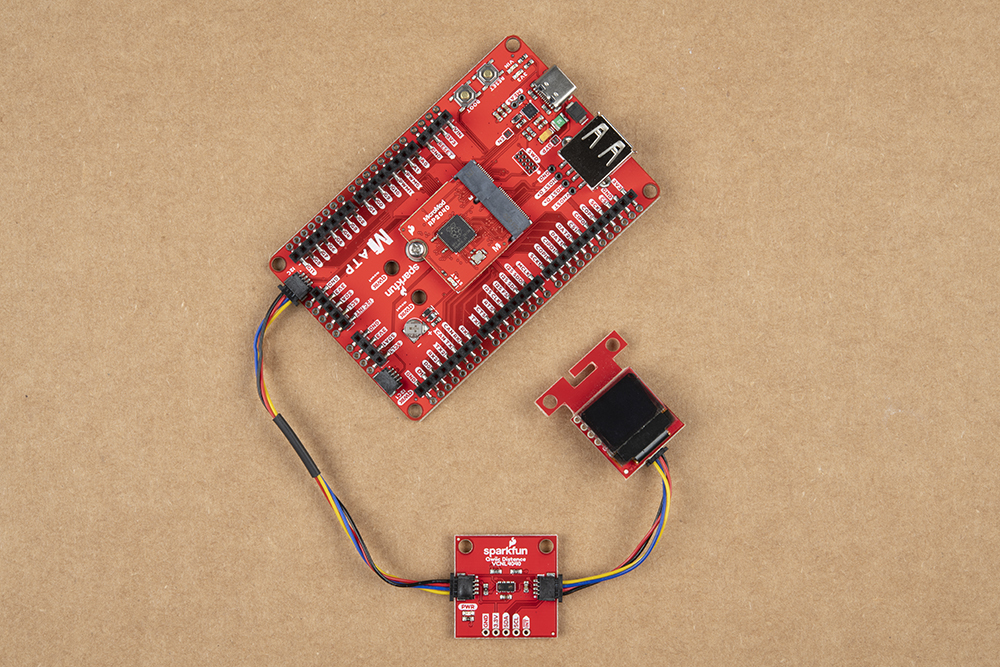
Qwiic-Enabled Device
If you decide to use a Qwiic device (because why not?!), simply insert a Qwiic cable between the two connectors. Note that not all Qwiic enabled devices have a MicroPython driver yet.
UF2 Bootloader
The MicroMod RP2040 processor board is easy to program, thanks the UF2 bootloader. With this bootloader, the board shows up on your computer as a USB storage device without having to install drivers for Windows 10, Mac, and Linux!
What is UF2?
UF2 stands for USB Flashing Format, which was developed by Microsoft for PXT (now known as MakeCode) for flashing microcontrollers over the Mass Storage Class (MSC), just like a removable flash drive. The file format is unique, so unfortunately, you cannot simply drag and drop a compiled binary or hex file onto the board. Instead, the format of the file has extra information to tell the processor where the data goes, in addition to the data itself. For more information about UF2, you can read more from the MakeCode blog, as well as the UF2 file format specification.
Software
There are two methods of programming the RP2040. You can use MicroPython or C/C++ depending your personal preference. The documentation is written for the Raspberry Pi's Pico development board but will apply for any board with the RP2040. Just make sure to adjust the pin definition depending on what GPIO is broken out.
Stay tuned for more information!
MicroPython Examples
The Raspberry Pi foundation has provided the necessary tools, documentation, and examples to get started with the RP2040. If you haven't already, check out the documentation on the Pico. We'll use this as a reference when using the chip on other development boards to fit your needs in this tutorial.
We'll be using the MicroPython examples from this GitHub repo using Thonny IDE.
Installing MicroPython on the RP2040
To install MicroPython on the RP2040, you will need to download the firmware from Raspberry Pi. Click below to head to the Raspberry Pi Foundation's MicroPython UF2 File for the RP2040. Click on the tab for the "Getting started MicroPython" and the button for Download UF2 File.
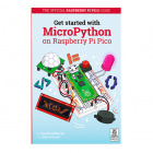
On your MicroMod carrier board, find the boot and reset button. Press and hold the boot button down with one finger.
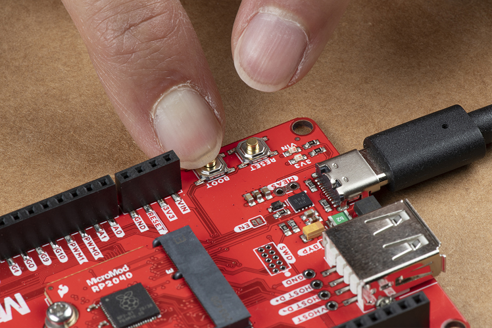
Press the reset button with momentarily with another finger.
 |
|
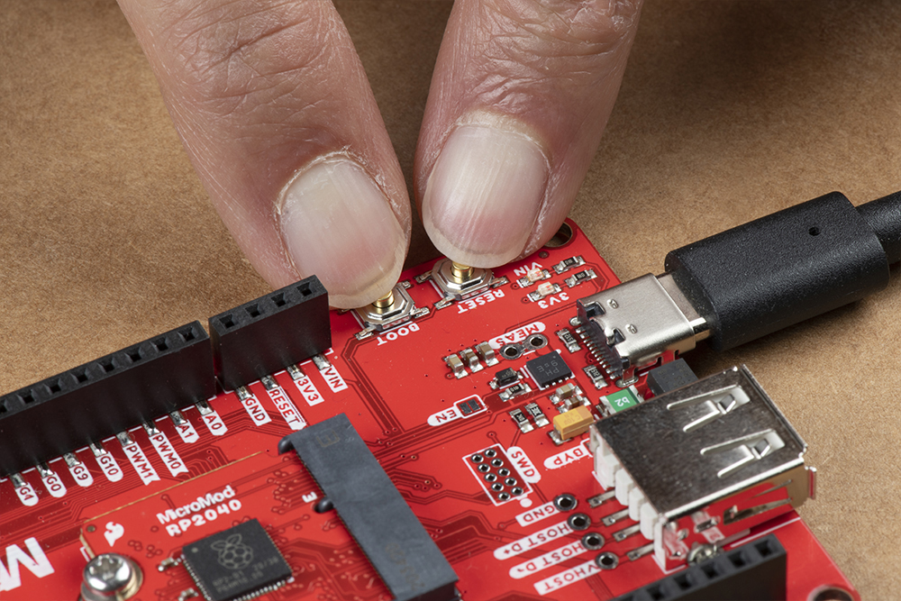
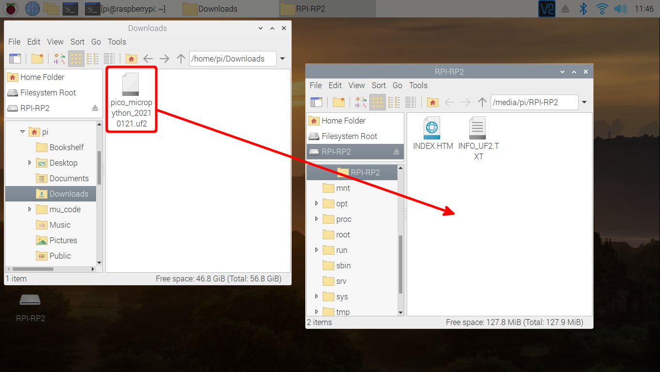
Release the boot button. The board should appear on your computer as a removable drive called RPI-RP2.
Draw and drop the UF2 file into the "removable drive". The board will automatically reboot. Below is an image highlighting the UF2 file being moved to a the removeable drive on a Raspberry Pi.
Configuring Thonny IDE
&& combines the two commands into a single line and the -y answers "yes" to any prompts.sudo apt update && sudo apt full-upgrade -y
thonny -v
INFO thonny:Thonny version: 3.3.3
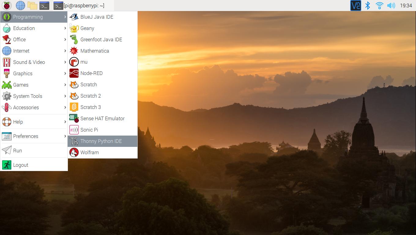
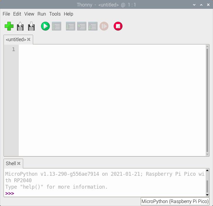
Open Thonny up from the start menu: Raspberry Pi Start Menu > Programming > Thonny Python IDE
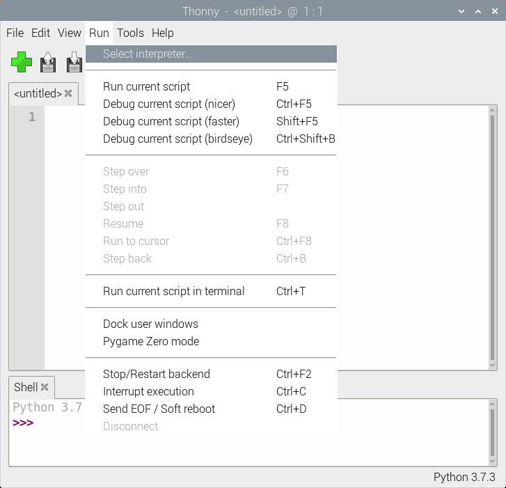
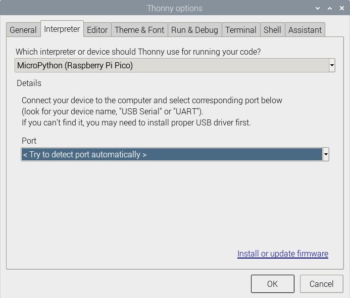
Set Thonny's interpreter for the RP2040. The "Raspberry Pi Pico" will work for the RP2040. Head to the menu and select: Run > Select Interpreter....
This will open a new window for the Thonny options. In the Interpreter tab, select MicroPython (Raspberry Pi Pico) as the interpreter.
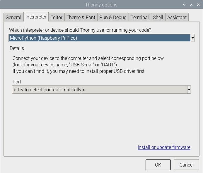
In the same window, make sure to select the option to have Thonny automatically detect the COM port for the board: Port > < Try to detect port automatically >
tty(AMA0 (/dev/ttyAMA0).
Hello World!
To check if this is working open the Thonny IDE, type the following into the editor. Feel free to adjust the message to whatever you prefer.
language:python
print("Hello world!")
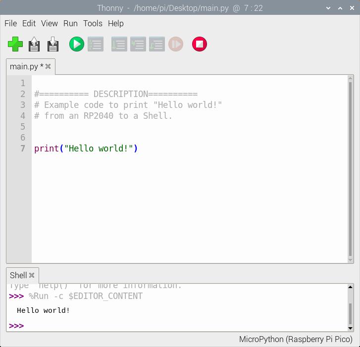
Hit the "Run current script" button. In the Shell, you will see the following output. Sweet!
language:bash
>>> %Run -c %EDITOR_CONTENT
Hello world!
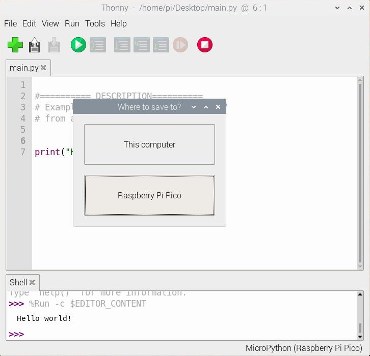
When a window pops up, select Raspberry Pi Pico.
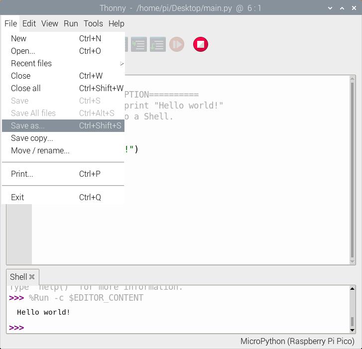
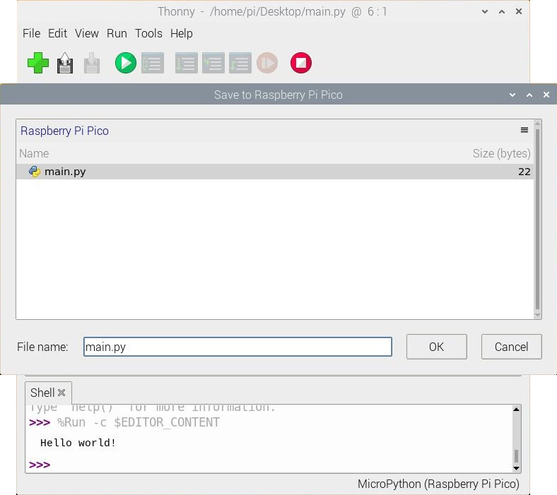
Then save the file as main.py
Just make sure to save any code that was edited on your computer (e.g. Save as... > This computer) before closing Thonny.

Blink
If you have the MicroPython examples saved, head to the following folder in your downloads .../pico-micropython-examples/blink/blink.py . Your code should look like the following. Of course, you can also copy and paste the code provided after the next paragraph as well.
language:python
# ========== DESCRIPTION==========
# The following code was originally written by
# the Raspberry Pi Foundation. You can find this
# example on GitHub.
#
#     https://github.com/raspberrypi/pico-micropython-examples/blob/master/blink/blink.py

from machine import Pin, Timer

led = Pin(25, Pin.OUT)
tim = Timer()
def tick(timer):
    global led
    led.toggle()

tim.init(freq=2.5, mode=Timer.PERIODIC, callback=tick)
Hit the "Run current script" button. Once the code runs, you will see the LED blink. If you want the board to run blink every time the board is powered up, just follow the note provided at the end the previous example.
Resources and Going Further
For more information, check out the resources below:
- Schematic
- Eagle Files
- Board Dimensions (PNG)
- Graphical Datasheet
- RP2040 Datasheet (PDF) (31.2 MB)
- Raspberry Pi Pico Datasheet (PDF) (16.5MB) - An RP2040-based microcontroller board
- Getting Started with Raspberry Pi Pico (PDF) (32.9MB) - C/C++ development with Raspberry Pi Pico and other RP2040-based microcontroller boards
- Raspberry Pi Pico C/C++ SDK (PDF) (2.14MB) - Libraries and tools for C/C++ development on RP2040 microcontrollers
- Raspberry Pi Pico Python SDK (PDF) (2.66MB) - A MicroPython environment for RP2040 microcontrollers
- RP2040 Informational Page
- GitHub Repo