SparkFun Qwiic Alphanumeric Display Hookup Guide
Hardware Overview
As mentioned in the introduction, the Qwiic Alphanumeric Displays use the VK16K33 LED driver chip to control the segments. In this section of the guide we'll go into more detail on the LED driver and the display, as well as the other components included on the board.
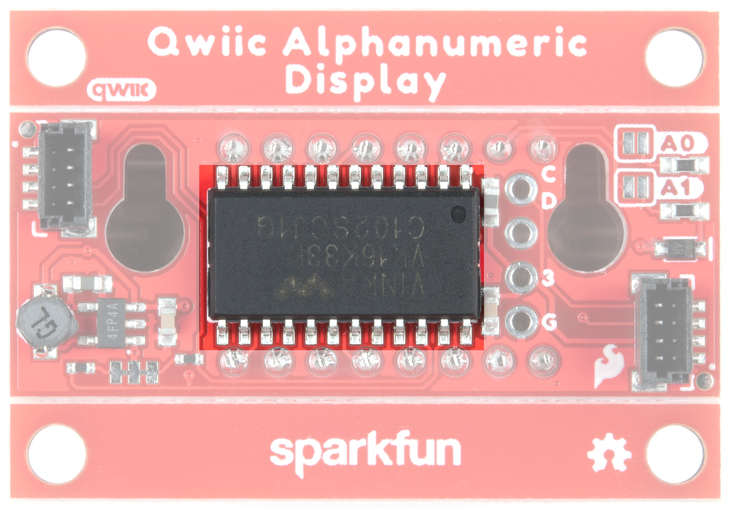
VK16K33 LED Driver
The Qwiic Alphanumeric Display boards use the VK16K33 LED driver chip to control the segments. The VK16K33 is a memory mapping and multifunction LED controller driver with a maximum display segment number of 128 patterns (16 segments and 8 commons) and a 13×3 matrix key scan circuit. There's an integrated RC oscillator and a 16-step dimming circuit as well. More information can be found in the VK16K33 Datasheet.
Alphanumeric Display
Look at all those beautiful segments ready to display (almost) whatever your heart desires!

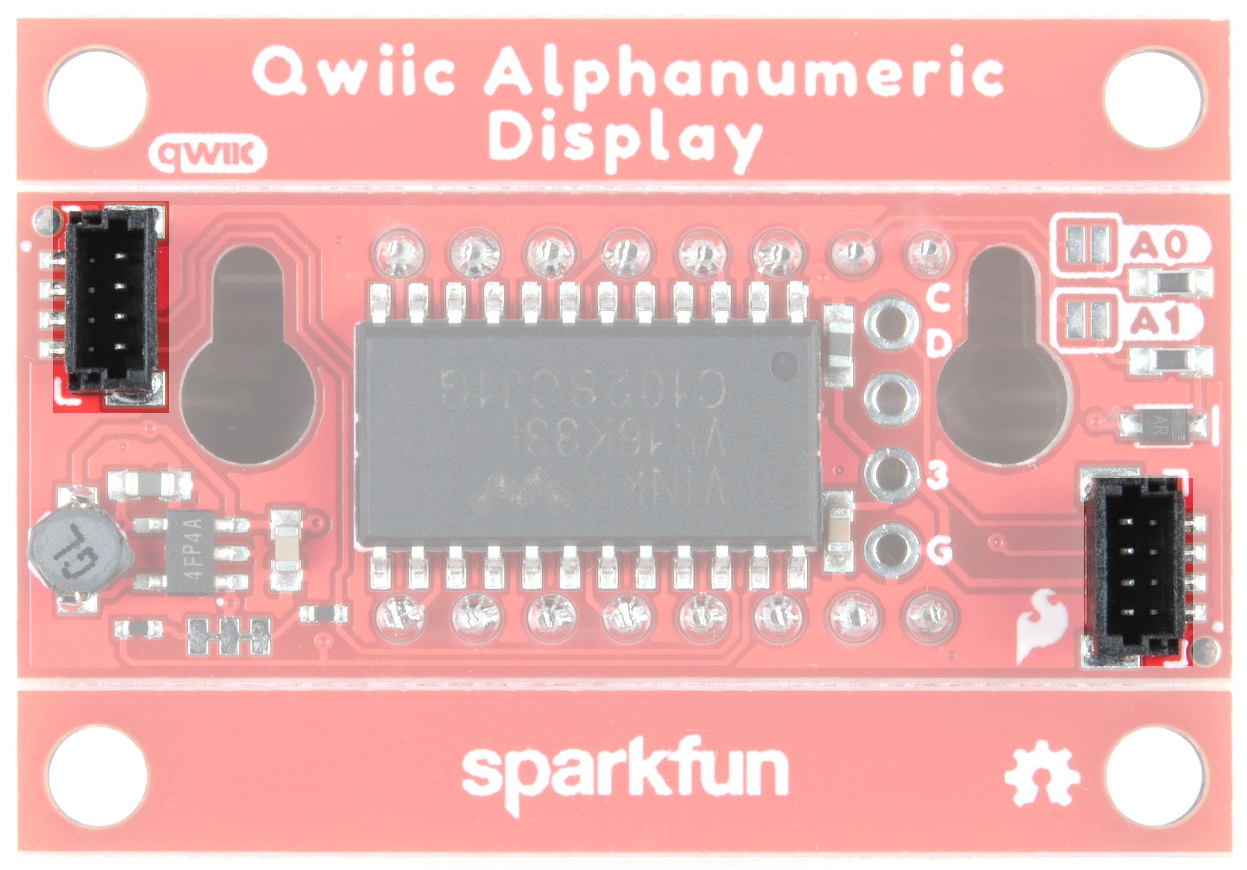
Qwiic
Our Qwiic Ecosystem makes sensors pretty much plug and play. There are two Qwiic connectors on either side of the Alphanumeric Display board to provide power and I2C connectivity simultaneously.
The default I2C address of the board is 0x70. Additional addresses are available - see the Jumpers section below.
I2C Address Jumpers
Two jumpers have been provided to allow you to choose the I2C address of the peripheral. See the table below for configuration details.
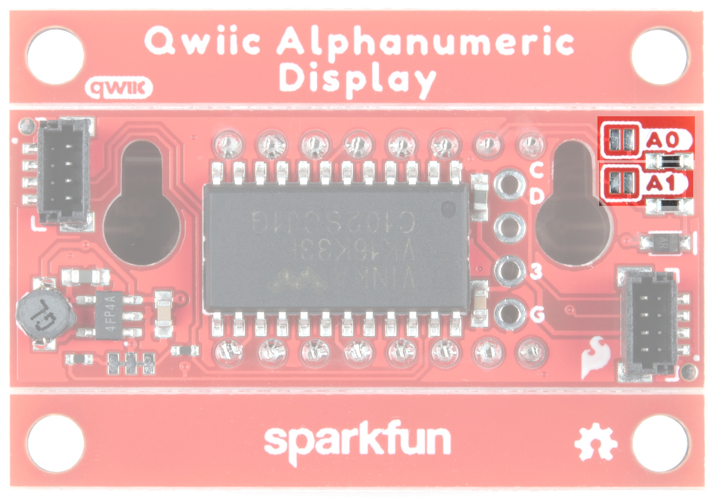
| Address | A0 | A1 |
|---|---|---|
| 0x70 | Open | Open |
| 0x71 | Closed | Open |
| 0x72 | Open | Closed |
| 0x73 | Closed | Closed |
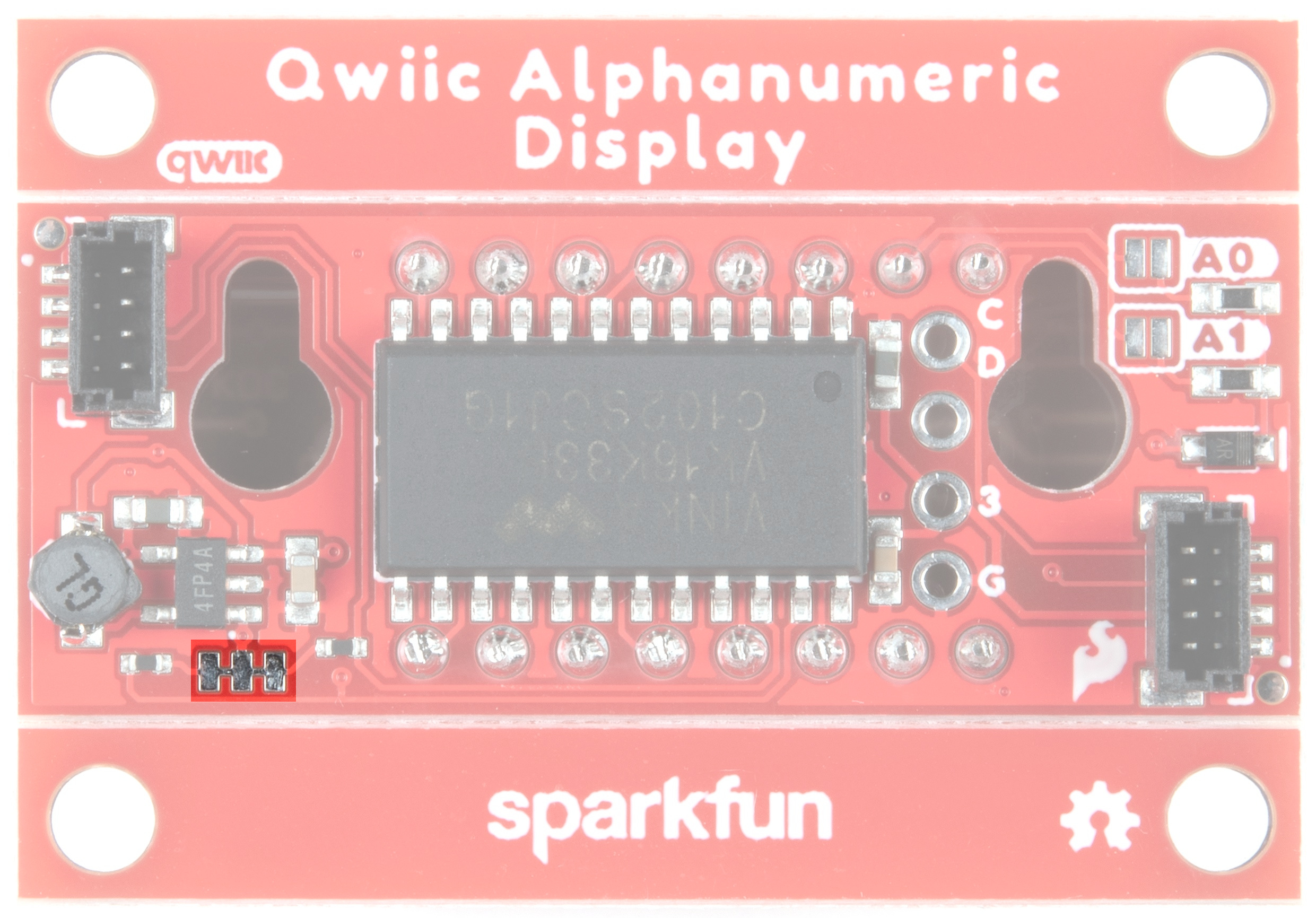
I2C Bus Resistor Jumper
The Qwiic Alphanumeric Display Breakout has onboard I2C pull up resistors; if multiple sensors are connected to the bus with the pull-up resistors enabled, the parallel equivalent resistance will create too strong of a pull-up for the bus to operate correctly. As a general rule of thumb, disable all but one pair of pull-up resistors if multiple devices are connected to the bus. If you need to disconnect the pull up resistors they can be removed by cutting the traces on the corresponding jumpers highlighted below.
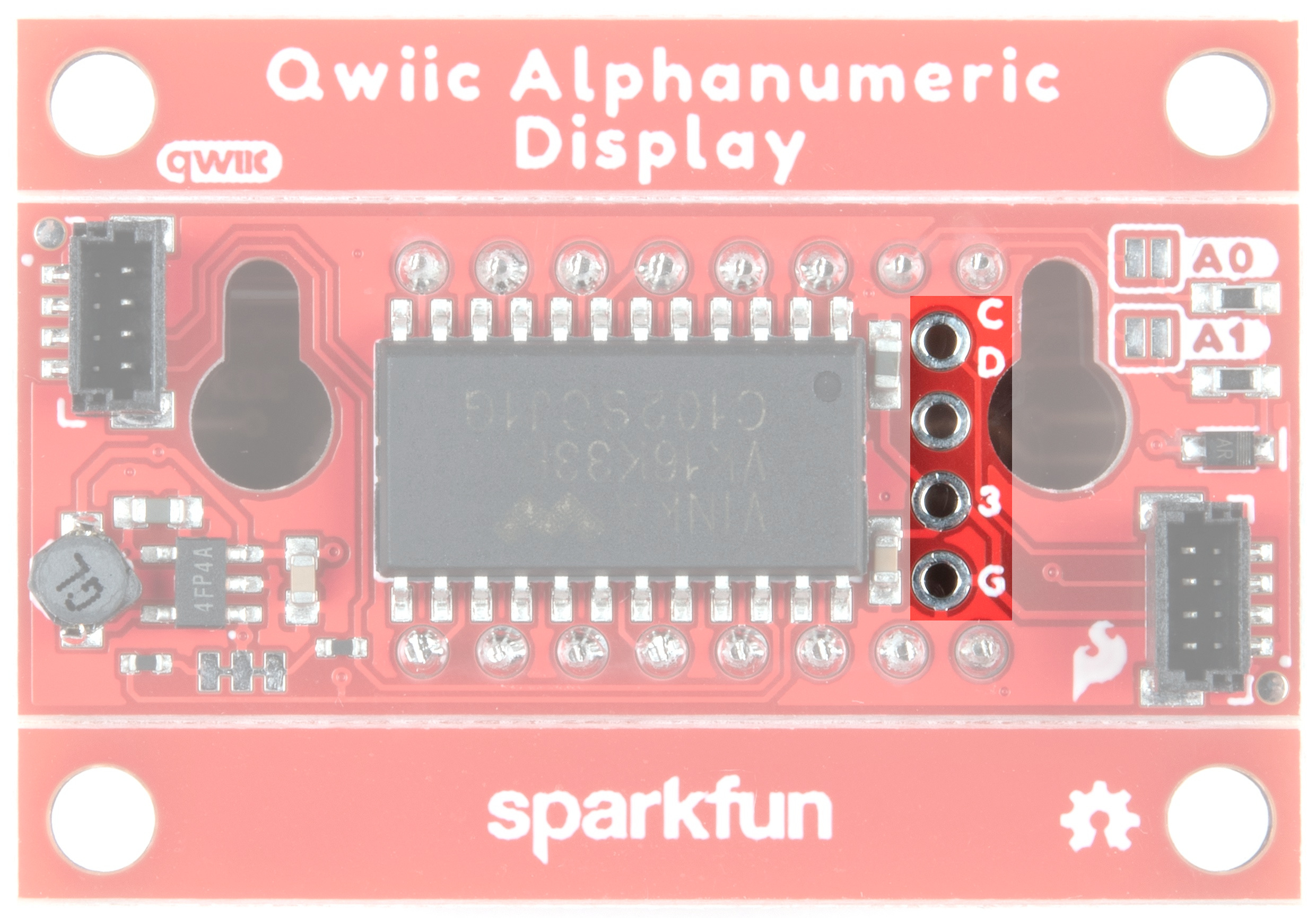
I2C Pins
If you've got mad soldering skillz and really want to access the I2C pins, we've made these bad boys available to you. Check it:
- C - SCL
- D - SDA
- 3 - 3.3V
- G - GND
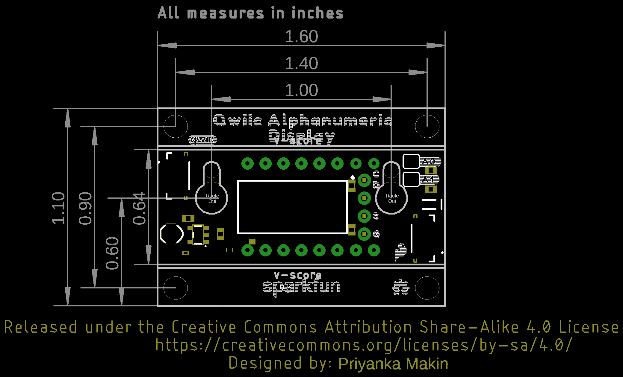
Board Outline
Each Alphanumeric Display Breakout board measures 1.6" x 1.1".