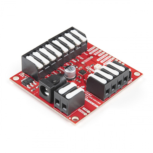
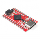
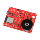
The SparkFun ProDriver utilizes the latest TC78H670FTG stepper motor driver from Toshiba. With a full to 1/128 stepping resolution and two different methods for control (serial communication or clock-in stepping) this is a great option for your next project that requires precise motor control.
Although both communication methods are included in the Arduino library, the serial command has some unique features. The serial communication allows users to precisely control the phase, torque, mixed decay ratio of each coil, and current limit while the motor is in motion. (In contrast, most stepper motor drivers need an external trimpot that is physically adjusted to control the current output limit.)
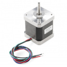
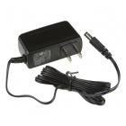
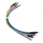
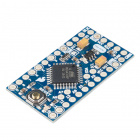
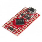
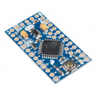
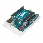
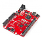
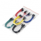
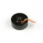
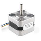
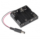
The SparkFun ProDriver does need a few additional items for you to get started. At minimum, users will want an Arduino compatible microcontroller with a USB cable, a power supply, some hookup wire or jumper wires, and a stepper motor (*we recommend a 4-wire, bipolar stepper motor to begin with). You may already have a few of these items, including the USB cable, so feel free to modify your cart based on your needs. Additionally, there are also alternative part options that are available as well (click button below to toggle options).
Here are a few other Arduino compatible microcontrollers. For a full list of options from our catalog, please visit the Arduino microcontroller product category.
Here are a few other wiring options. For a full list of options from our catalog, please visit the wire product category.
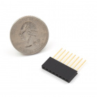
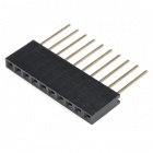
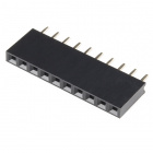
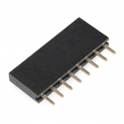
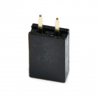
While the ProDriver is intended to be solderless, users may want headers to work with.
Here are a few other stepper motor options. For a full list of options from our catalog, please visit the stepper motor product category.
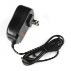
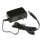
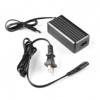
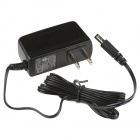
Here are a few other power supply options. For a full list of options from our catalog, please visit the power supply and wall adapter product categories.
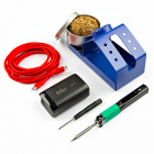
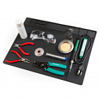
Although the ProDriver is intended to be solderless, if you would like to modify the jumpers or solder the wiring, you will need soldering equipment and/or a hobby knife.
We will skip over the more fundamental tutorials like Ohm's Law and What is Electricity?. However, below are a few fundamental tutorials that may help users familiarize themselves with various aspects of this board.
Below, is a basic drawing of the board dimensions and component layout for the SparkFun ProDriver. For more detailed measurements, users should download and open the Eagle files from the GitHub repository or from the Documents tab on the product page.
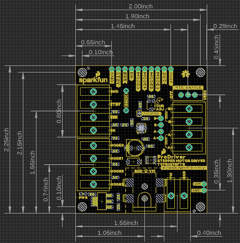
For more details on the DC barrel jack, 2-pin latch terminal, and 4-pin latch terminal's dimensions, check out the documentation on their respective product pages.
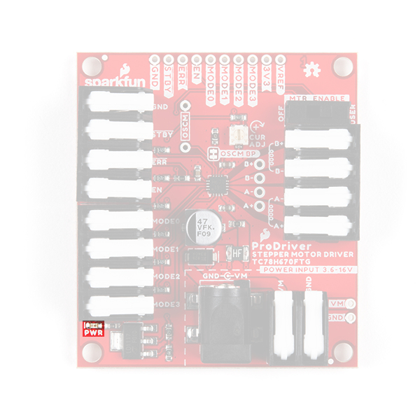
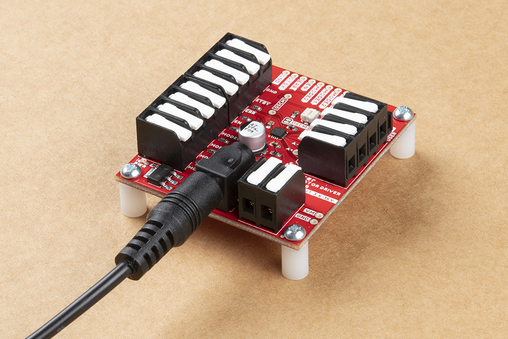
To power the ProDriver, users will need a power supply that has an output of 3.3 - 16V and can source at least 2A. We have provided three different methods for users to connect their power supply to the ProDriver:
VM and GND) for users who wish to, more permanently, solder their power connections.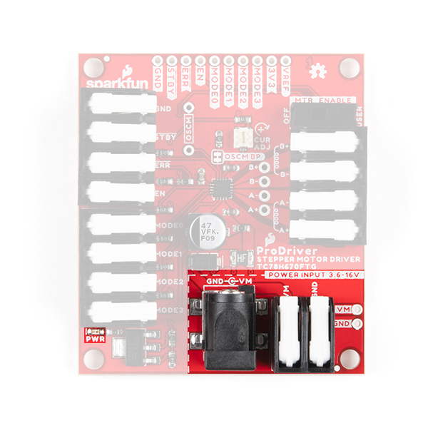
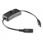
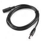
Users opting to use the DC barrel jack may find some of these accessories useful:
⚡ Note: Do not connect or disconnect the motor while the ProDriver is powered; as it may damage the motor driver IC.
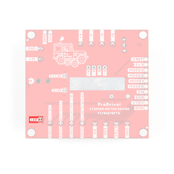
A power LED status indicator is also provided on the ProDriver. The LED turns on once the motor power supply is connected and the attached voltage regulator outputs 3.3V. The LED can be disabled by cutting the LED jumper.
LED jumper on the ProDriver. (Click to enlarge) A 3.3V PTH connection is broken out amongst the other pin connections. It is connected to the 3.3V output of the LM117 voltage regulator, which is powered by the motor power supply input.
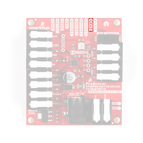
3V3 PTH pin on the ProDriver. (Click to enlarge) The ProDriver includes a safety features to protect the board and power supply. There is a protection diode to prevent reverse current and a thermal fuse to prevent current from being overdrawn.
⚡ Note: We have provided bypass jumpers for more advance users to circumvent these safety features; however, we recommend NOT modifying them, unless you absolutely know what you are doing. Users can easily damage or destroy their ProDriver and/or power supply by modifying the jumpers.
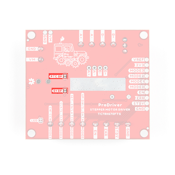
D1 BP and PTC BP jumpers on the ProDriver. (Click to enlarge)
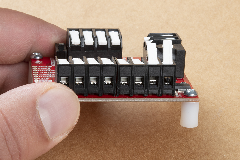
The ProDriver was designed with latch pins to provide a completely solderless connection to get users up and running faster. We have also broken out those same connections with PTH points, for a more permanent installation. (*These latch pins are great! Just as secure as a screw pin terminal, but without the hassel.)

More details on these pins are laid out in the following sections below, excluding the power pins. Details for the 3V3 and VM pins are described in the power section above.
When working with the latch terminals, there are two things to keep in mind. These should be fairly obvious, once you take a closer look at the jaws or clamping mechanism:
The input control pins are used to interface directly with the TC78H670FTG motor driver. The ProDriver was designed with latch pins to provide a completely solderless connection to get users up and running faster. We have also broken out those same connections with PTH, for a more permanent installation. (*These latch pins are great! Just as secure as a screw pin terminal, but without the hassel.)
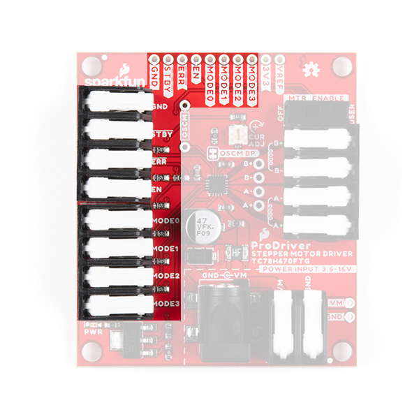
For more details on the functions of the pins listed below, check out the datasheet for the TC78H670FTG.
| Pin Name | Label | Description | Operating Something |
|---|---|---|---|
| Ground Reference | GND |
Ground (i.e. the 0V reference) | 0V |
| Standby | STBY |
This pin is used to either place the motor driver in standby or initiate one of the control methods.
|
0 to 3.3V (Default: Low or 0V) |
| Enable | EN |
When the motor driver is configured for clock-in stepping, this pin is used to enable the motor output ON or OFF.
|
0 to 3.3V (Default: Low or 0V) |
| Error Detection Flag Output | ERR |
If a thermal shutdown (TSD), over current (ISD), or motor load
open (OPD) error, is triggerd, the pin output is pulled low. Under a normal operating status, the level of ERR pin is equal to the EN control voltage from outside. The error flag can be released by reconnecting the VM power or by setting the device to standby.
|
0 to 3.3V |
|
MODE0 UP-DW (Clock-in) S_DATA (Serial) |
MODE0 |
MODE0: Utilized to configure the conrol method of the motor driver, when the standby pin is released. Based upon that control method, the pin will then function as one of the following inputs:
|
0 to 3.3V (Default: High or 3.3V) |
|
MODE1 SET_EN (Clock-in) LATCH (Serial) |
MODE1 |
MODE1: Utilized to configure the conrol method of the motor driver, when the standby pin is released. Based upon that control method, the pin will then function as one of the following inputs:
|
0 to 3.3V (Default: High or 3.3V) |
|
MODE2 CLK (Clock-in) S_CLK (Serial) |
MODE2 |
MODE2: Utilized to configure the conrol method of the motor driver, when the standby pin is released. Based upon that control method, the pin will then function as one of the following inputs:
|
0 to 3.3V (Default: High or 3.3V) |
|
MODE3 CW-CCW (Clock-in) |
MODE3 |
MODE3: Utilized to configure the conrol method of the motor driver, when the standby pin is released. The pin will then, only function as an input for clock-in stepping:
|
0 to 3.3V (Default: High or 3.3V) |
| Current Threshold Reference | VREF |
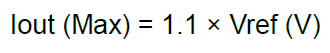
Connected to the 10 kΩ potentiometer that controls the maximum drive current to the stepper motor coils. Iout (max) = 1.1 × Vref (V) | 0 to 1.8 V |
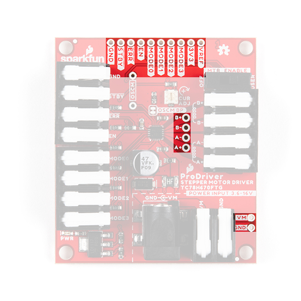
3V3 pin is connected to the 3.3V output of the LM117 voltage regulator, which is powered by the motor power supply input. The 3.3V ouptut is utilized as a supply voltage for the voltage divider that controls the maximum drive current through the VREF pin. The supply voltage is also utilized as an I/O reference voltage through the pull-up resistors connected to the MODE0, MODE1, MODE2, and MODE3 pins.The output channel pins are used to drive the coils of the stepper motor. The paired outputs are connected to the two H-Bridges of the motor driver.
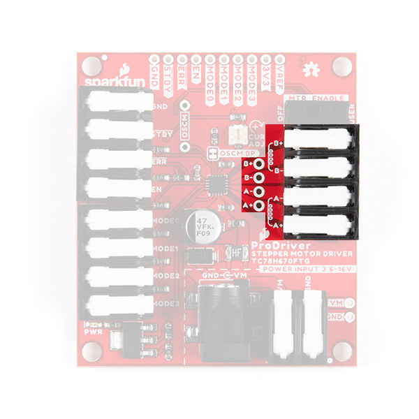
| Pin Name | Label | Description |
|---|---|---|
| Positive "A" Channel Output | A+ |
The "A" channel motor output (+) pin |
| Negative "A" Channel Output | A- |
The "A" channel motor output (-) pin |
| Positive "B" Channel Output | B+ |
The "B" channel motor output (+) pin |
| Negative "B" Channel Output | B- |
The "B" channel motor output (-) pin |
For basic information on stepper motors, users should check out our Motors and Selecting the Right One tutorial. Additionally, we have included a few YouTube videos, below, that help explain the theory of the stepping functionality behind stepper motors. Users who have stepper motors with more than four wires, may also find this article enlightening.
The ProDriver is driven by the Toshiba TC78H670FTG stepper motor driver IC. The TC78H670FTG is a 2-phase stepping motor driver, intended for bipolar stepper motors. The chip features two H-Bridge motor drivers that provide users with step size resolutions ranging from full steps, half steps, and micro-stepping down to a 1/128 of a step. The TC78H670FTG can be controlled with the standard clock-in stepping, but it also has an additional option for serial communication.

Some of the advantages to the TC78H670FTG over a simple H-Bridge, include a standby function, selectable mixed decay, error detect flag output, clock- in stepping or serial communication control, software control of the current output, and a minimal parts bill of matierals (BOM). The serial command method is especially unique because it allows users to precisely control the phase, torque, current limit and mixed decay ratio of each coil during the motor operation. Additionally, while in most stepper motor driver ICs, an external trimpot is required to set the current limit; however, with the ProDriver, a simple serial command can be utilized to precisely adjust the current limit.
| Characteristic | Description |
|---|---|
| Motor Power Supply Voltage: | 2.5 to 16.0V |
| Output Current: | 2.0A (max) |
| Control Methods: |
|
| Clock Frequency: |
|
| Step Size Resolution: |
Discrete Steps
Micro-Steps
|
| Error Detection Functions: |
|
On the ProDriver the EN and ERR pins are broken out separately; however, these connections are tied to the same pin on the TC78H670FTG, which operates as a control input and output for error flags. A typical application of the EN/ERR pin with a microcontroller is displayed below.
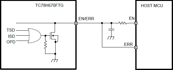
EN/ERR pin application from the datasheet. (Click to enlarge) This duality allows the TC78H670FTG to give users control of the power to the motor drive channels; while also providing autonomous functionality to disable its own power, when an error flag is triggered and simultaneously, provide an output indicator on the same pin.
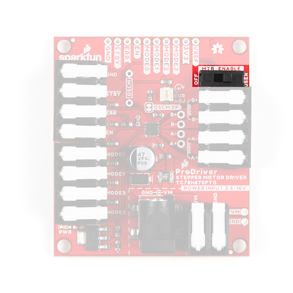
EN and ERR pins. (Click to enlarge) The EN pin controls the ON/OFF operation of the H-Bridges to the motor outputs. When the EN pin is low, all of the H-Bridge MOSFETs turn off and become high impedance (Hi-Z). Likewise, when the EN pin is set high, the motor channel outputs will be driven normally, based on the stepping controls.
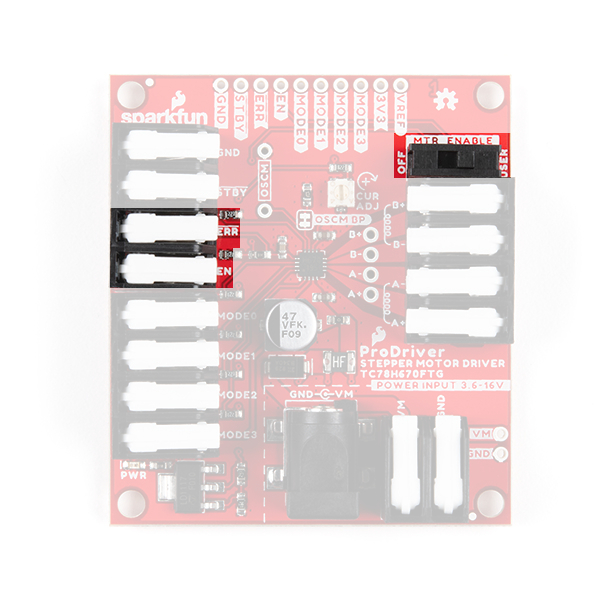
EN pin functionality from the datasheet. (Click to enlarge) VM power-on and power-off cycles by setting the EN pin low to disable the motor channel outputs. The EN pin can be set high after the power supply reaches the target voltage and becomes stable.We have broken out EN pin control to a DPST switch. The switch allows users to easily disable power to the motor channels without connecting additional hardware.
EN pin. (Click to enlarge) The TC78H670FTG has a built-in functionality to detect thermal shutdown (TSD), over current (ISD), or motor load
open (OPD) connection issues. When these errors are triggered, the ERR pin is pulled low. In a normal operating status, the level of ERR pin is equal to the EN control voltage from outside. After the error is triggered, the error flag can be released by reconnecting the VM power or by setting the device to standby.
The standby pin for the TC78H670FTG, is used to set up the control method for the motor driver. When the standby pin is low, the motor is released from any control methods and is in standby. On the up edge, of when the standby pin is set high, the motor driver is configured for clock-in stepping or serial communication control based on the input state of the MODE0, MODE1, MODE2, and MODE3 pins.

HIGH. Pulled from the datasheet. (Click to enlarge) There are two different communication or control methods for users to interface with the ProDriver. The control method is configured by the input state of the MODE0 - MODE3 pins, when the TC78H670FTG is released from standby mode. The TC78H670FTG features the common clock-in stepping method and a more unique serial communication control.
This method is unique to the TC78H670FTG Toshiba motor driver. The control logic allows users to manipulate registers through serial communication, which provide control over:
(*For more details on the configuration options for the available registers, refer to Section 9 of the datasheet.)
This is a standard method for controlling most stepper motor drivers. By default, the ProDriver is configured for clock-in stepping in the fixed mode with a step resolution of 1/128 of a step.
MODE0 - MODE3 pins after releasing the standby pin, when the clock-in control method is configured. Below, is a table from the datasheet of the step resolution settings.
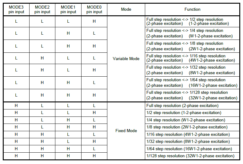
Once clock-in stepping and the step resolution are configured together. The TC78H670FTG awaits for the up-edge of the clock (CLK) signal, for the MODE2 pin, to before it shifts the motor’s electrical angle per step. The MODE3 pin, controls the clockwise/counter-clockwise (CW-CCW) rotation direction of the motor for clock-in stepping.
MODE3 pin is low, the motor is driven with a counter-clockwise (CCW) operation.MODE3 pin is high, the motor is driven with a clockwise (CW) operation.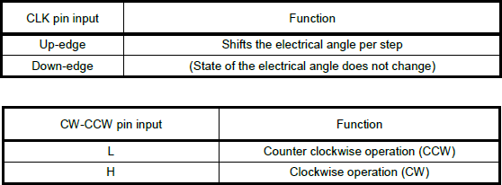
MODE3 (CLK) and MODE2 (CW-CCW) pin functionality for clock-in stepping, from the datasheet. (Click to enlarge) In variable mode, users can transition between different ranges of step size resolutions with the MODE0 and MODE1 pins. To enable the transition between step size resolutions, the MODE1 (SET_EN) pin must be high, when the TC78H670FTG is in variable mode for clock-in stepping. The MODE0 (UP-DW) pin is used to control the direction of the step size transition.
MODE0 pin is low, the step size resolution is increased to a smaller step size (i.e. from 1/4 to 1/8 of a step).MODE0 pin is high, the step size resolution is decreased to a larger step size (i.e. from 1/8 to 1/4 of a step).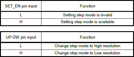
MODE1 (SET_EN) and MODE0 (UP-DW) pin functionality for transitioning the step size resolution during clock-in stepping, from the datasheet. (Click to enlarge) The transition between step size resolutions occurs, synchronously with the up-edge of the next clock signal. It should also be noted, that the transition can only change the step size resolution one increment at a time (i.e. it takes three clock cycles to transition from a 1/4 step size, down three sizes, to a 1/32 step size resolution).
The maximum drive current for the ProDriver is limited to 2A (max). However, the peak output current can be controlled with two different methods.
Hardware: The first method controls the drive current through the reference voltage (Vref). The reference voltage, can be configured utilizing the external potentiometer or VREF breakout pin.

VREF pin that can be utilized to control the maximum drive current. For the hardware control, the maximum drive current can be calculated with the following equation:
Software: The second method controls the drive current through software. Utilizing serial communication to the TC78H670FTG, the registers can be configured to limit the maximum drive current. The maximum drive current can be calculated with the following equation, based on the configured registers:

Chopping is a technique that is used to control the average current per phase, by rapidly switching a relatively high output voltage to the motor coils, on and off. This technique improves the current rise time in the motor and improves the torque at high speeds, while maintaining a high efficiency in the constant current drive.
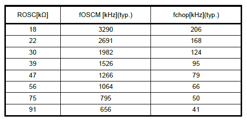
On the TC78H670FTG, the OSCM oscillation frequency (fOSCM) and chopping frequency (fchop) are adjusted with an external resistor (ROSC), connected to the OSCM pin. By default, a 47 kΩ resistor is utilized. However, users can modify the ROSC resistor value by cuttin the OSCM BP jumper and soldering a resistor to the provided OSCM PTH connections.
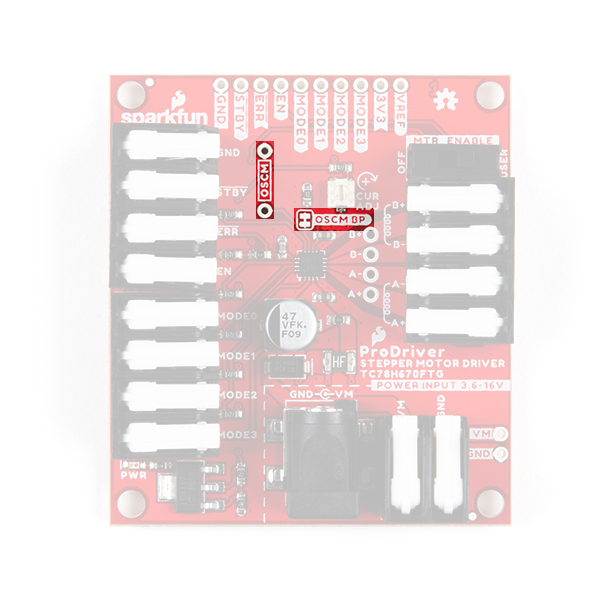
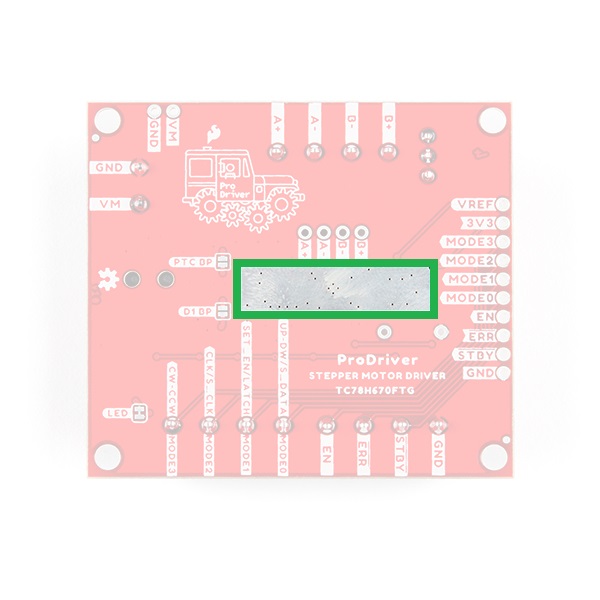
OSCM BP jumoer and OSCM PTH points on the ProDriver. (Click to enlarge) There is a thermal ground plane on the bottom of the board available for users to attach a heat sink(s) with some thermal tape, if necessary. However, after several tests by the engineer for this product, we have determined that for most use cases, a heat sink probably won't be necessary.
Please bear with us, while we work on getting this information released. Thank you!
On the Prodriver, we recommend one of our wall adapter, power supplies to connect to the DC barrel jack. Otherwise, users can utilize the (VM and GND) PTH or latch pins to attach an external power supply. REMEMBER to disconnect the power before connecting/disconnecting your motor.
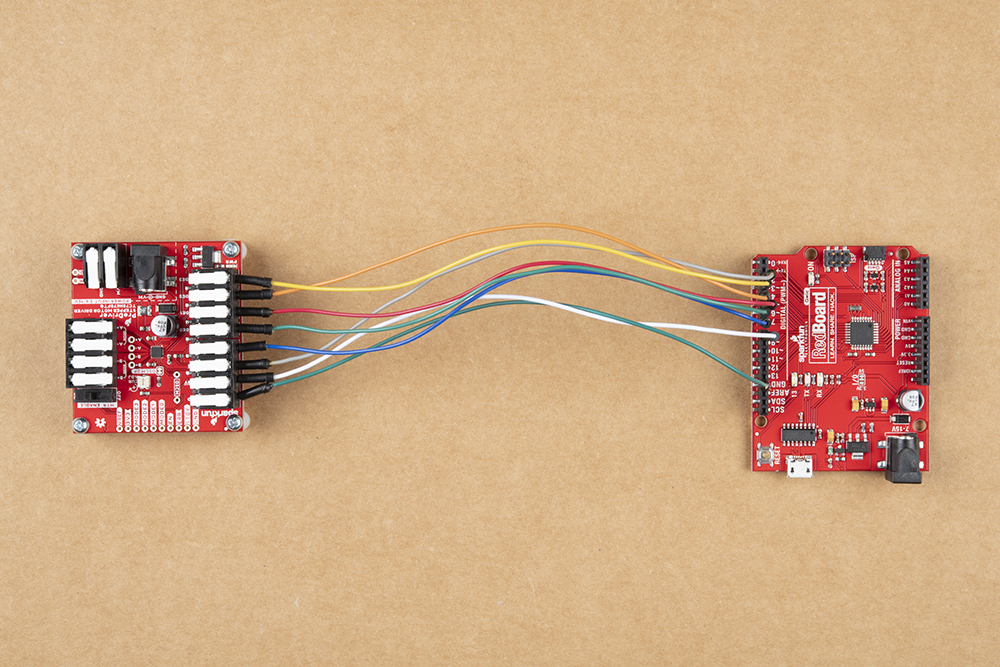
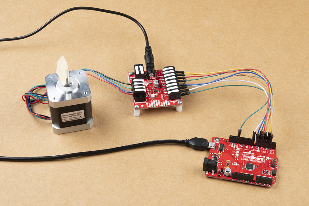
The input control pins need to be connected to a microcontroller. To utilize the Arduino examples below, without modifying the code, we recommend using the SparkFun RedBoard (Qwiic) as the microcontroller. Use the table and image below to hookup the SparkFun RedBoard to the ProDriver with some jumper wires.
| ProDriver Control Pins | STBY |
EN |
MODE0 |
MODE1 |
MODE2 |
MODE3 |
ERR |
|---|---|---|---|---|---|---|---|
| RedBoard Pins | D8 |
D7 |
D6 |
D5 |
D4 |
D3 |
D2 |
MODE 1 pins. Each ProDriver board requires a seperate pin on the microcontroller to operate their MODE 1 pin. (See the example below)The output channels for the H-Bridges need to be connected to the stepper motor. Users need to hookup the wire pairs for each coil to individual channels. However, the polarity of the connections isn't very important as the direction of the motor rotation can be controlled in software. For the recommended stepper motor, use the table and image below to hookup the motor to the ProDriver.
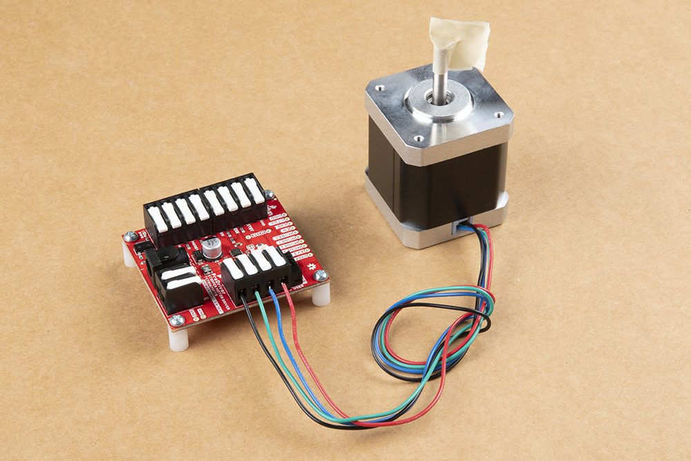
| Motor Driver Output Channels | A+ |
A- |
B+ |
B- |
|---|---|---|---|---|
| Stepper Motor Wires | Black | Green | Red | Blue |
⚡ Note: Do not connect or disconnect the motor while the ProDriver is powered; as it may damage the ProDriver.
In order to determine the wire pairs for each coil on their stepper motor, users can refer to the datasheet for the stepper motor. Often, the relevant information is indicated as shown in the diagram below.
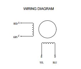
For a 4-wire motor, users can alternatively use a multimeter to determine the wire pairs for the coils. This is done by comparing the resistance of one wire and against each of the three remaining wires. Whichever wire shows the lowest resistance against the first wire is the pair mate. The remaining two wires should show similar resistance between the two of them.
Utilizing the instructions above, an example of the standard assembly used for most of the examples in the Arduino library, is shown below.
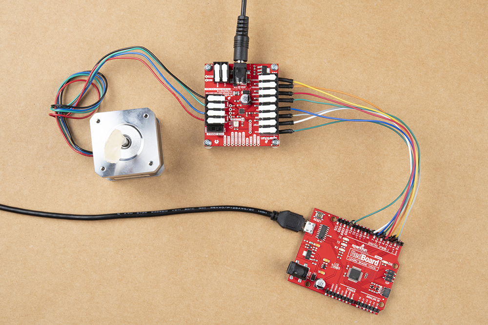
| ProDriver Control Pins | STBY |
EN |
MODE0 |
MODE1 |
MODE2 |
MODE3 |
ERR |
|---|---|---|---|---|---|---|---|
| RedBoard Pins | D8 |
D7 |
D6 |
D5 |
D4 |
D3 |
D2 |
For users interested in utilizing multiple ProDrivers, we have provided an additional Arduino example for hooking up two ProDrivers in parallel. Use the table and image below to hookup the SparkFun RedBoard to the two ProDrivers with some jumper wires.
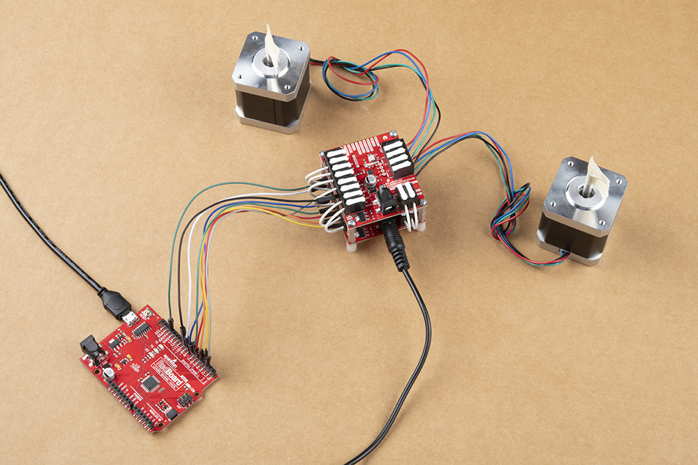
MODE 1 pins. Each ProDriver utilizes a different pin on the RedBoard, for their MODE 1 pin.| ProDriver (1) Control Pins | STBY |
EN |
MODE0 |
MODE1 |
MODE2 |
MODE3 |
ERR |
|
|---|---|---|---|---|---|---|---|---|
| ProDriver (2) Control Pins | STBY |
EN |
MODE0 |
MODE1 |
MODE2 |
MODE3 |
ERR |
|
| RedBoard Pins | D8 |
D7 |
D6 |
D5 |
D9 |
D4 |
D3 |
D2 |
Note: This example assumes you are using the latest version of the Arduino IDE on your desktop. If this is your first time using Arduino, please review our tutorial on installing the Arduino IDE. If you have not previously installed an Arduino library, please check out our installation guide.
We've written a library to easily get setup and control stepper motors with the SparkFun ProDriver. However, before we dive into spinning motors, let's take a closer look at the available functions in the library. You can install this library through the Arduino Library Manager. Search for SparkFun ProDriver TC78H670FTG Arduino Library and you should be able to install the latest version. If you prefer manually downloading the libraries from the GitHub repository, you can grab them here:
Let's get started by looking at the functions that set up the SparkFun ProDriver:
In the global scope, construct your device object (such as myProDriver) without arguments.
PRODRIVER myProDriver;
Below, are the available methods, which can be called:
.begin() - Initializes the motor driver with basic settings. It also returns false if error is detected (i.e. ERR pin is pulled low by the IC)..pinSetup() - Configures pins as inputs/outputs as needed, and to default settings (disabled, standby)
.enable() - Enables power to the motor output channels.
.diable() - Disables power to the motor output channels.controlModeSelect() - This configures the IC into the mode specified by the settings.controlMode variable..errorStat() - This function checks the status of the ERR output, which is triggered for thermal shutdown (TSD), overcurrent (ISD), or motor load open (OPD) errors..step(steps, direction, clockDelay) - Utilizes the CLOCKIN mode to step the motor a set amount of steps in a specified direction.changeStepResolution(resolution) - Used to change the step resolution with clock-in stepping.sendSerialCommand() - With the serial communication method, this function sends a serial command, if one of the settings for the serial control is modified.
settings.phaseAsettings.phaseBsettings.currentLimAsettings.currentLimBsettings.torquesettings.openDetectionsettings.mixedDecayAsettings.mixedDecayBsettings.phasePosition.stepSerial(steps, direction, stepDelay) - Used with the serial communication method, to rotate the motor for a specified number of steps and direction.
stepSerialSingle(direction) - Used with the serial communication method, to rotate the motor with a single step in a specified direction..setTorque(newTorque) - A wrapper function to set desired torque setting.
sendSerialCommand() is called.PRODRIVER_TRQ_100 (default set in constructor)PRODRIVER_TRQ_75PRODRIVER_TRQ_50PRODRIVER_TRQ_25.setCurrentLimit(currentLimit) - A wrapper function to set desired current limit setting.
VREF, and affected by the torque setting. The changes will not take effect on the motor driver until sendSerialCommand() is called.
currentLimit (10-bit value: 0-1023)Note: Most of the examples in the Arduino library will use a standard setup for the ProDriver (shown below), with the exception of the Example8_SerialMultiMotor demo code.
The first example in the Arduino library is perfect for demonstrating the basic functionality of the ProDriver. In the Arduino IDE, the example file can be found in the File > Examples > SparkFun ProDriver TC78H670FTG Arduino Library > Example1_Basic drop down menu. The example, utilizes the default configuration of the Arduino library and steps the motor utilizing clock-in control.
Example 8 demonstrates the operation of multiple ProDrivers through a parallel connection. In the Arduino IDE, the example file can be found in the File > Examples > SparkFun ProDriver TC78H670FTG Arduino Library > Example8_SerialMultiMotor drop down menu. The example, configures the microcontroller to sequentially operate multiple ProDrivers.
If users experience a jittery response from their motor or their motor missteps, try increasing the drive current with the potentiometer.
VREF pin that are utilized to control the maximum drive current. For more on the SparkFun ProDriver (TC78H670FTG), check out the links below:
For more motor control tutorial, check out the links below:
Or check out this blog post for inspiration
learn.sparkfun.com | CC BY-SA 3.0 | SparkFun Electronics | Niwot, Colorado