SparkFun Line Follower Array Hookup Guide
Contributors:
 MTaylor
MTaylor 
Hardware Overview
The array PCB has a few pieces to note.
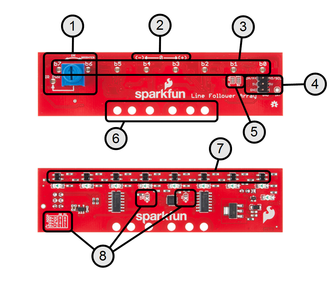
- IR brightness control and indicator -- The IR PWR led shows the strength of the IR LEDs. Brighter means more IR emitted.
- Polarity marking -- Shows getPosition() polarity.
- Robot vision indicators -- See what the IR sensors are picking up. Note: these are not inverted by the library's set/clearInvertBits() functions. Usage covered in Setting the Brightness
- Digital interface -- Described in the Assembly section.
- I2C pull option jumper -- Defaulted to 3.3V pull-up. Can be converted to 5V if necessary. See Setting the Jumpers.
- Mounting holes -- The inner two holes fit the Shadow chassis. Others are general purpose.
- The IR transducers -- These emit and detect IR radiation.
- I2C address selection -- Set the jumpers in accordance with the table for a desired address.
Electrical Specifications
| Parameter | Conditons | Min | Typ. | Max | |
|---|---|---|---|---|---|
| Supply Current |
Vcc = 5.0v Strobing disabled |
25 |
185 |
mA | |
| Vcc = 5.0v Strobing enabled Running 'MostBasicFollower' |
16 | 100 | 160 | mA | |
| Read Cycle TIme |
Vcc = 5.0v Strobing Enabled |
3.2 |
ms |
||
| Vcc = 5.0v Strobing Disabled |
250 | us |