SparkFun Line Follower Array Hookup Guide
Contributors:
 MTaylor
MTaylor 
Assembly
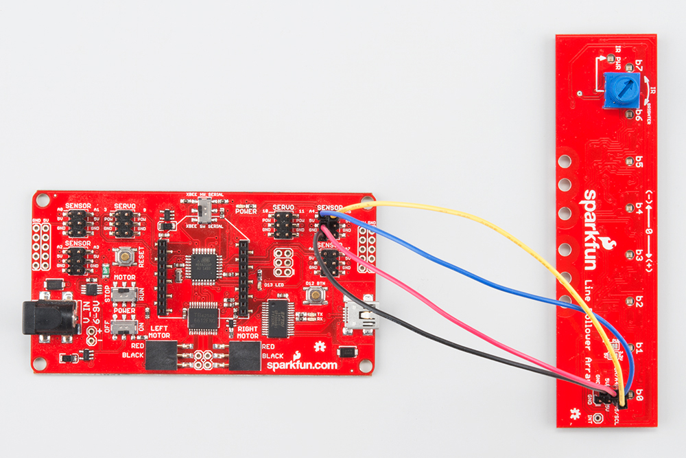
Assembly is super easy! Make the following connections with your microcontroller.
| Signal/Description |
Line Follower Silkscreen |
RedBot Mainboard Silkscreen |
RedBoard Silkscreen |
|---|---|---|---|
| Power - 5v DC |
5V |
5V | 5V |
| Ground | GND | GND | GND |
| I2C Data |
SDA/A4 | A4 | A4 or SDA |
| I2C Clock |
A5/SCL |
A5 | A5 or SCL |
| INT(*) | NC | NC | NC |
* Note: INT pin is not required but can be connected to any input if the interrupt functionality is programmed into the SX1509 expander.

Using I2C via pins A4 and A5.

Using I2C via the dedicated SDA and SCL pins.
Connections are pin compatible with the RedBot Mainboard.
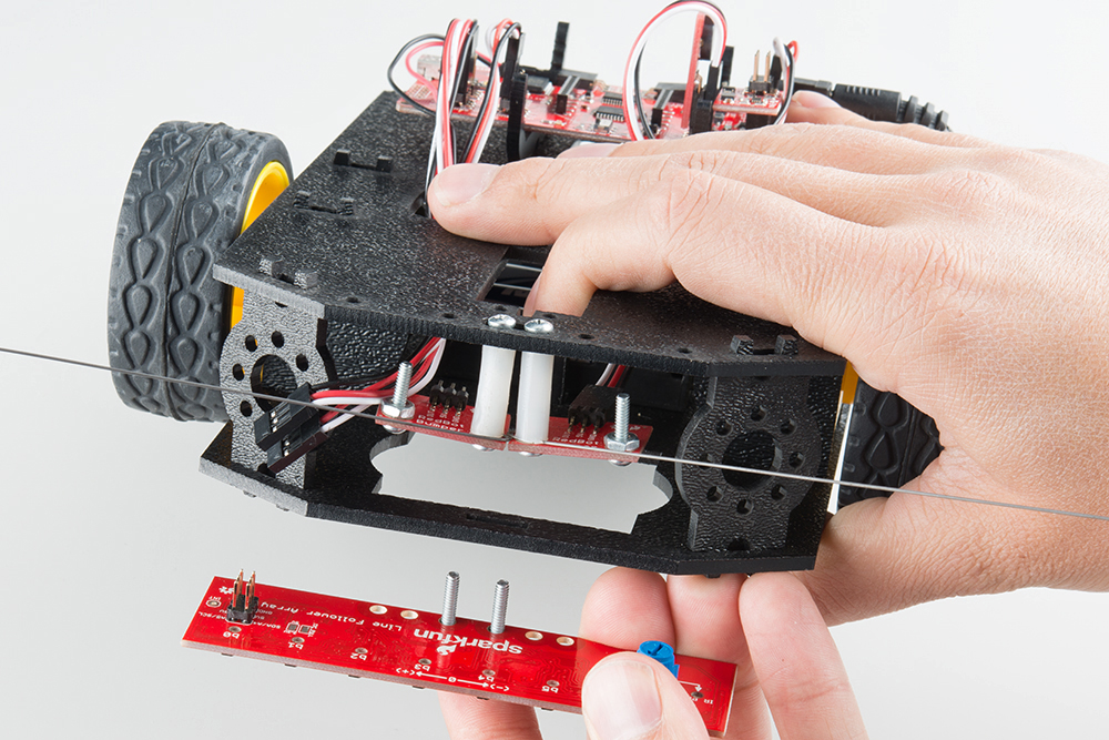
Mechanical Attachment to a Shadow Chassis
Attaching to the Shadow Chassis happens through the slot where the original three line following sensors were placed. Put 4-40 hardware through the array and hold with a finger. Hold the bolts through the slot in the shadow chassis, thumb on the 4-40 nuts, then make the electrical connections.
Hold the bolts in place with a finger
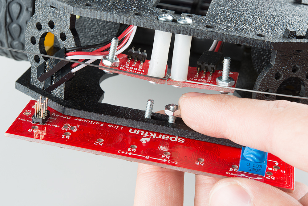
Thumb on the attaching nuts, then torque by hand or with a screwdriver
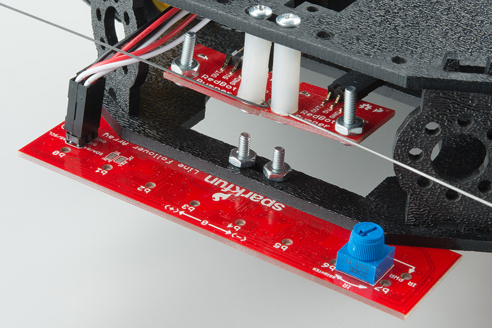
Make the electrical connections