SparkFun Indoor Air Quality Sensor - ENS160 (Qwiic) Hookup Guide
Hardware Overview
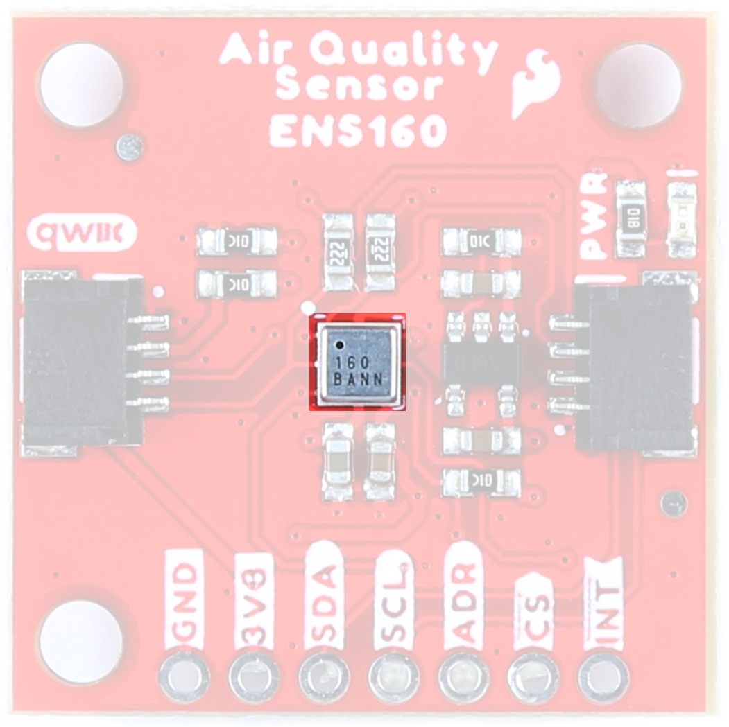
ENS160 Digital Metal-Oxide Multi-Gas Sensor
The ENS160 from ScioSense is a digital multi-gas sensor consisting of four independent heaters and gas sensor elements based on metal oxide (MOX) technology, and a controller. TrueVOC® air quality detection provides outputs such as eCO2, TVOC and AQI in compliance with worldwide IAQ standards.
The ENS160 includes a standard 2-wire digital I2C interface (SCL, SDA) or 4-wire digital SPI interface (SCLK, MOSI, MISO, CSn) for communication to the main host processor. For more information, refer to the datasheet.
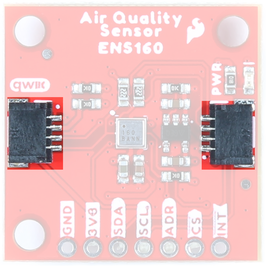
Qwiic Connectors
Our Qwiic Ecosystem makes sensors pretty much plug and play. There are two Qwiic connectors on either side of the Indoor Air Quality Sensor - ENS160 Sensor board to provide power and I2C connectivity simultaneously.
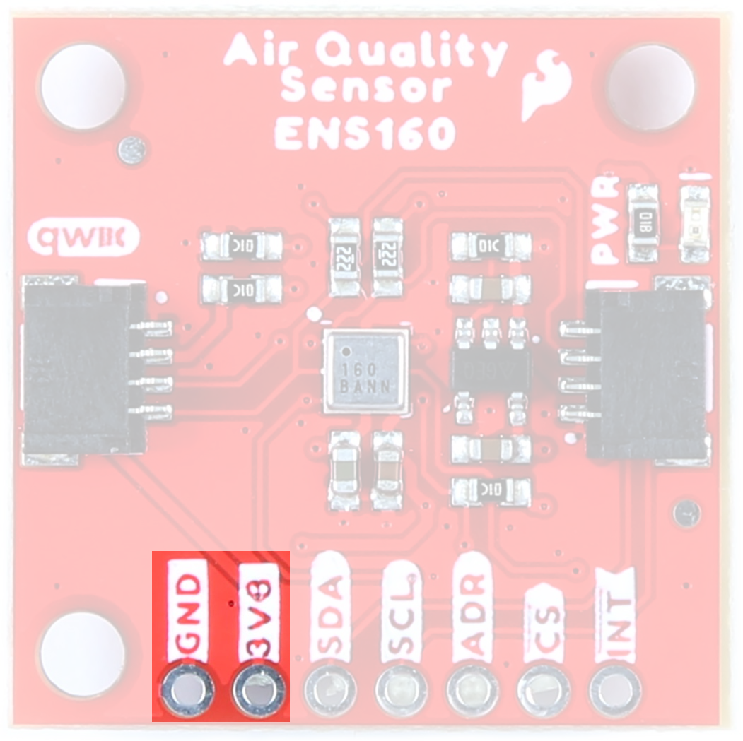
Power
Ideally, power will be supplied via the Qwiic connectors on either side of the board. Alternatively, power can be supplied through the header along the bottom side of the board labeled 3V3 and GND. The ENS160 functions at 1.8V so an on-board regulator
VDD input range is 1.71-1.98V, VDDIO input range is 1.71-3.6V.
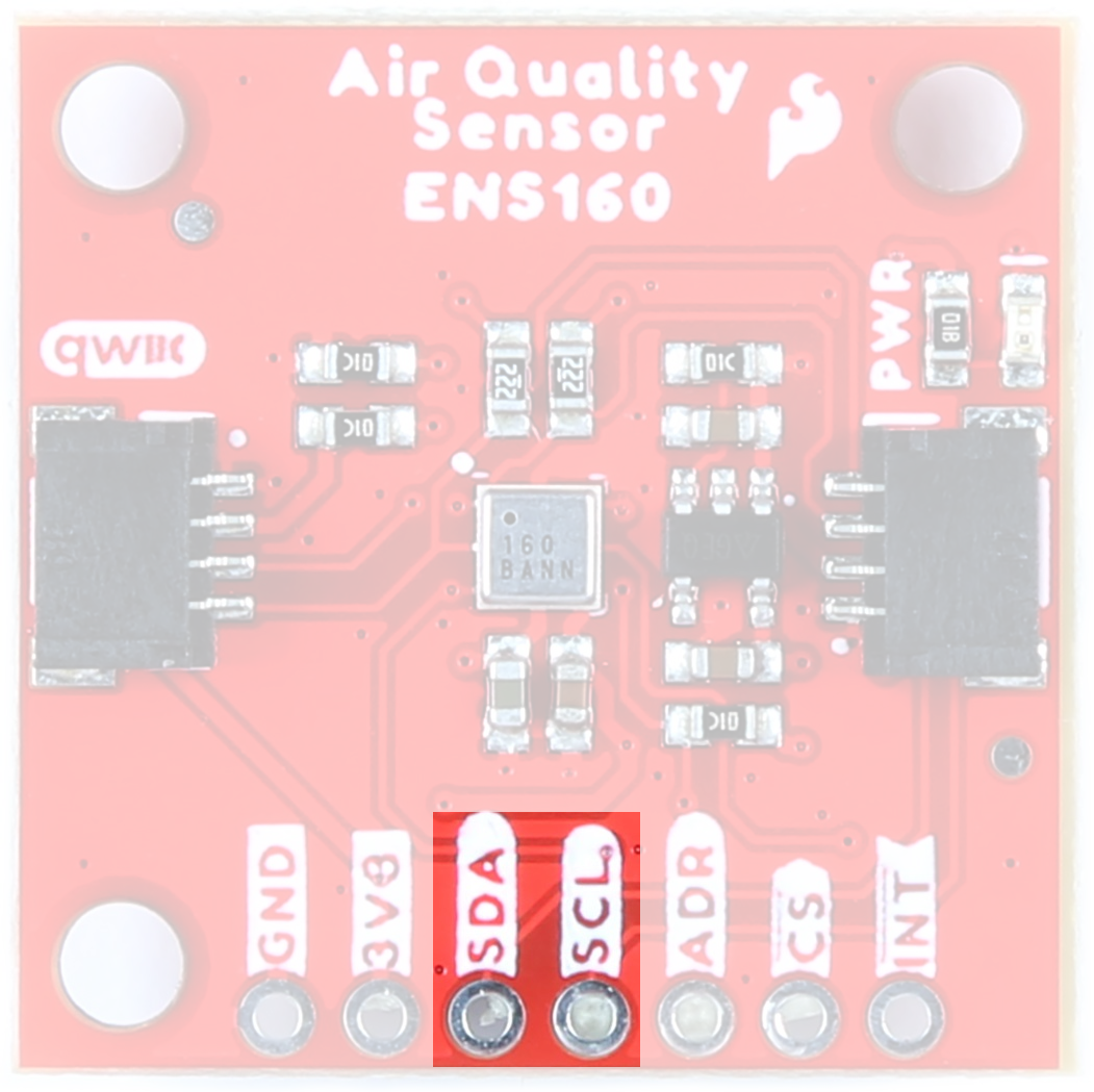
I2C Pins
The I2C pins break out the functionality of the Qwiic connectors. Depending on your application, you can connect to these pins via the plated through holes for SDA and SCL.
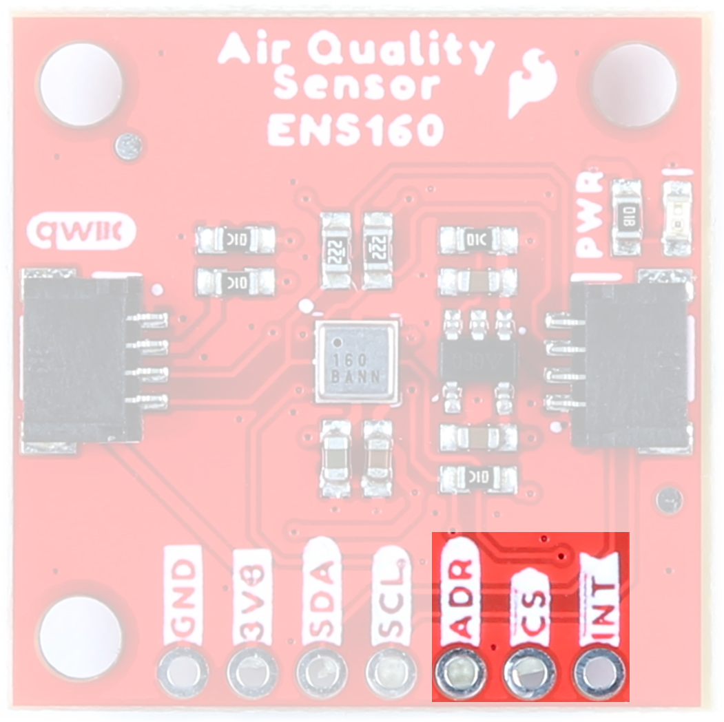
ADDR/POCI, Chip Select, and Interrupt Pins
The ADDR/POCI and Chip Select Pins are for use with SPI functionality. The interrupt pin is broken out to use for triggered events.
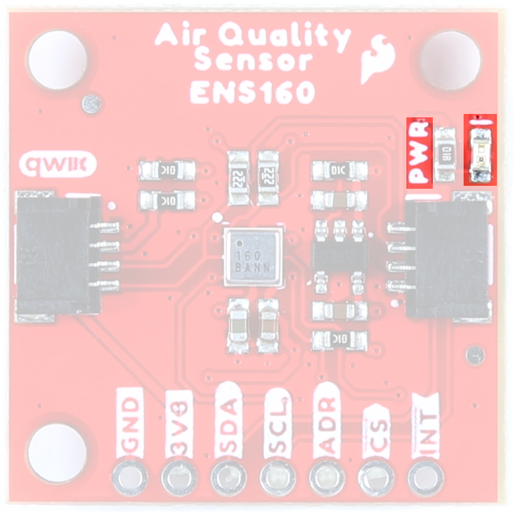
Power LED
When power is supplied to the board, this LED will light up.
Jumpers
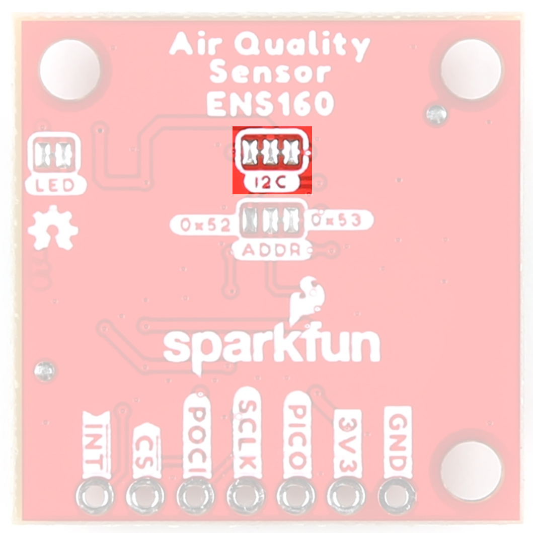
I2C Jumper
Like our other Qwiic boards, the Indoor Air Quality Sensor comes equipped with pull-up resistors on the clock and data pins. If you are daisy-chaining multiple Qwiic devices, you will want to cut this jumper; if multiple sensors are connected to the bus with the pull-up resistors enabled, the parallel equivalent resistance will create too strong of a pull-up for the bus to operate correctly. As a general rule of thumb, disable all but one pair of pull-up resistors if multiple devices are connected to the bus. To disable the pull up resistors, use an X-acto knife to cut the joint between the two jumper pads highlighted below.
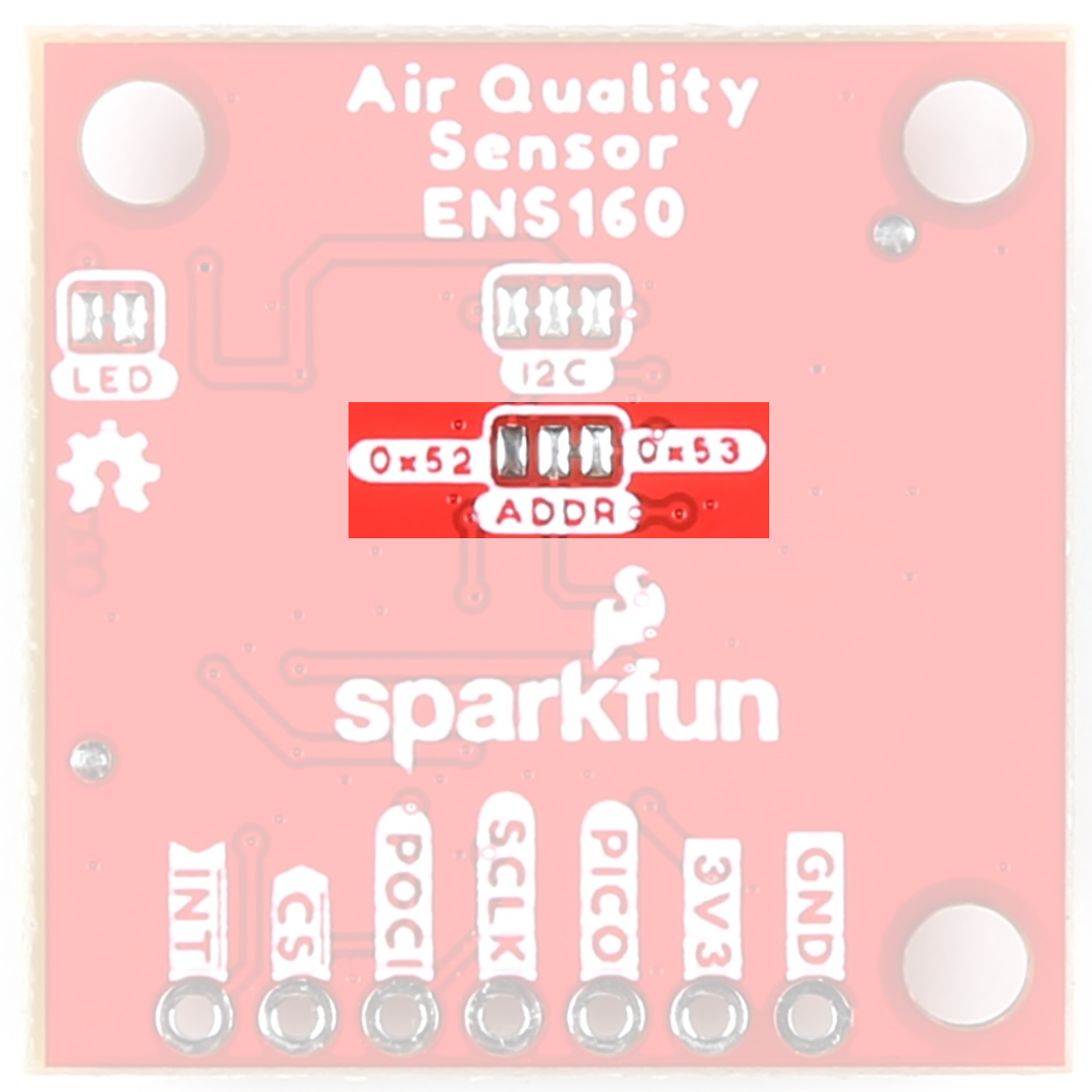
Address Jumper
By default, the 7-bit un-shifted I2C address of the board is 0x53. However, by manipulating the jumper on the back of the board, this address can be changed:
| ADDR | |
|---|---|
| VDD | 0x53 (Default) |
| GND | 0x52 |
| OPEN | Undefined |
LED Jumper
If power consumption is an issue, cutting this jumper will disable the Power LED on the front of the board.

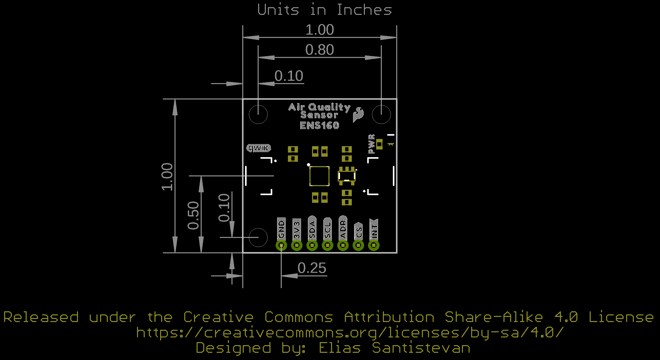
Board Outline
Like most of our standard Qwiic boards, the SparkFun Indoor Air Quality Sensor - ENS160 measures 1 inch by 1 inch.