Most of you probably have done a science experiment that required data of some sort to be recorded. In which case, the data often had a temporal component that also needed to be recorded...
The gator:RTC is a real-time clock. This means that the gator:RTC can be used as a supplemental data logging tool, in conjunction with the gator:log to add precise timing to your data collection. Therefore, student(s) can put down that stopwatch and start focusing more attention on what is happening in their experiments. Other applications for the gator:RTC include time lapse photography, timers and alarms, clocks, and etc.
This tutorial will show you how to get started using this gator:RTC with the gator:bit (v2) in the micro:bit development environment.
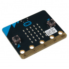
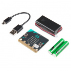
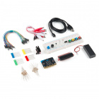
To get started, you'll need a micro:bit to control everything. Each of the products below includes a micro:bit, but the kit and bundle also include some additional accessories that you may want as well.
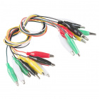
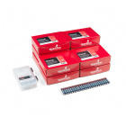
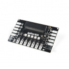
To easily use the gator board ecosystem, a gator:bit (v2) will help breakout the necessary pins and you will also need alligator and/or banana cables to connect the gator:bit to the gator:RTC.
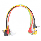
(*These banana cables have a special diameter on the attachment points designed specifically for use with the micro:bit ecosystem. They may or may not be compatible with the banana cables used on your test equipment.)
You may already have some of these materials, so feel free to modify your cart as necessary.
The gator:RTC sensor is pretty straight forward to use in application. However, you may find the following concepts useful along the way.
If you aren't familiar with the micro:bit, we recommend reading here for an overview.
We would also recommend taking a look at the following tutorials if you aren't familiar with them.
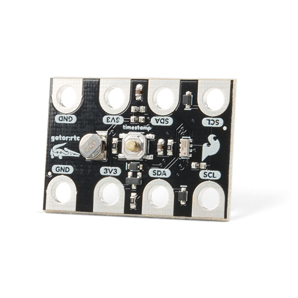
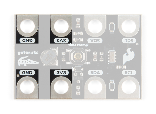
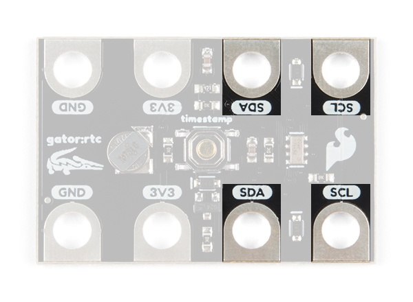
The gator:RTC consists of 4 pads for power and data.
| Contacts | Direction | Description |
|---|---|---|
| GND | N/A | Ground: Reference voltage and ground loop. |
| 3.3V | In | Power: Provides 3.3V to board. |
| SDA | Bi-directional | Data: Data and commands are transmitted between the RV-3028 and microcontroller. |
| SCL | In | Clock: The microcontroller provides the timing needed to communicate on the data line. |
The specified operating voltage for the RV-3028 is between 1.2 - 5V. For use with the gator:bit (v2) and micro:bit, you should provide 3.3V through the 3V3 and GND pads to keep the logic levels consistent.
The board also includes a 1mAh lithium-metal rechargeable, coin type backup battery. This allows the RTC module to keep track of time even when power to the board is cut (for low power applications). Although, current consumption varies by how the RTC is operating and the temperature, users should expect a fully charged backup battery to last for several months with the RTC operating conservatively.

Here are some of the characteristics of the battery from the datasheet:
| Characteristic | Range |
|---|---|
| Nominal Voltage | 3.0V |
| Nominal Capacity | 1.0mAh (3.1V - 2.0V) |
| Discharge Current | 5µA |
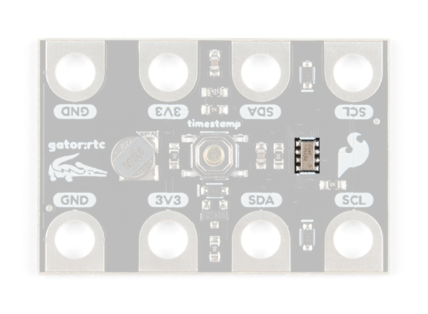
The RV-3028 is an extremely low power real-time clock (RTC), consuming only 40 - 60nA on average at 3V, which interfaces over an I2C bus. A real-time clock is used to keep track of the current time, which is a useful, but often forgotten tool. For the most part, users will only need to know I2C addresses of this board to prevent address conflicts with other devices or sensors.
Here are some of the characteristics of the RV-3028 RTC, for details, check out the datasheet and application manual:
| Characteristic | Range |
|---|---|
| Operating Voltage | 1.2V to 5V |
| Supply Current (@3V) |
40nA to 60nA (avg.) (~330nA peak) 5µA to 40µA (active I2C-bus) 95nA to 150nA (backup battery operation) |
| Operating Temperature | -40°C to 85°C |
| Xtal (Internal Oscillator) Frequency | 32.768 kHz (± 5ppm @ 25°) |
| Timing Accuracy | Factory calibrated: ± 1ppm @ 25°C (no temp. compensation) |
| Calender Range | Automatic leap year correction: 2000 to 2099 |
| Counter | Seconds, minutes, hours, date, month, year and weekday |
| I2C Address |
7-bit Peripheral Address: X1010010b, where X is the R/W bit
0x52 - Write Address
0xD2 - Read Address |
Time is the continuous progression of events which succeed one another from the past and into the future. By most human standards, time is measured in a base unit of time, called a second. Most recently, the second (SI unit of time) was re-defined to a more specific standard:
It is defined by taking the fixed numerical value of the cesium frequency ΔνCs, the unperturbed ground-state hyperfine transition frequency of the cesium-133 atom, to be 9,192,631,770 when expressed in the unit Hz, which is equal to s-1.
Below, are additional resources regarding the topic of time:
RTC stands for real-time clock, which is used to keep track of time. With the convenience of modern electronics such as computers, smartphones, GPS navigation, and IoT/smart devices, the importance of an RTC can be easily overlooked. An RTC is different from an oscillator or hardware clock that only generates a clock signal; the primary difference being that an RTC can keep track of the time. In the case of the gator:log, the RV-3028 is is able to keep track of time by the month, day (including weekday), year (leap-year accurate from 2000 to 2099), hours (12-hour format), minutes, and seconds. This is useful for a variety of applications including, but not limited to data logging, timers, and other long duration projects like time-lapse photography.
The key benefits of using an RTC in your project is that they are:
The drawbacks of an RTC that should be considered before using it in your project are:
The RTC is most useful for long duration projects. Here is a list of some examples:
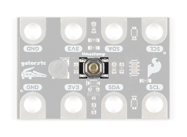
In addition to tracking time, the gator:RTC also includes a time stamp button to mark events. When pressed, the RV-3028 stores a time stamp of the button press. Therefore, it queried consistently, this button can be used to mark significant events in a data log. For example, marking the end point of a pH titration in a data set.
I2C is a communication protocol used to transfer data between controller and peripheral devices. It is a 2-wire connection consisting of SDA (data) and SCL (clock). The protocol is pretty well defined so it can be shared with multiple devices. This is beneficial for daisy chaining multiple devices together on a single bus. The primary thing users will need to watch out for is address conflicts (you can't have devices with the same address).
Connecting your gator:RTC to the gator:bit (v2) is simple. The board can also be daisy-chained with other I2C boards. This can easily be done with alligator cables or these special banana cables.
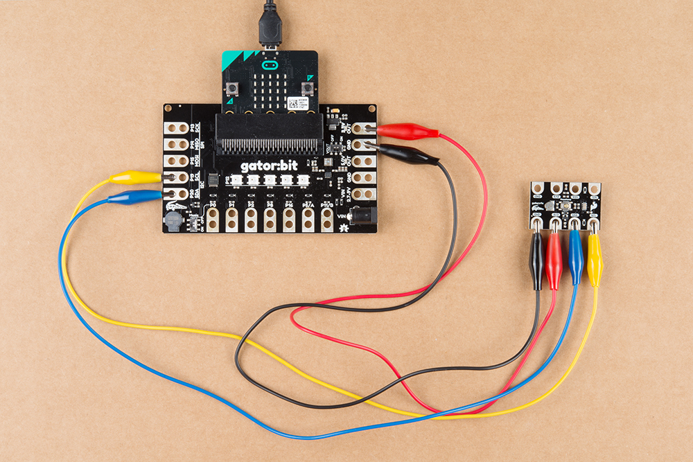

| Gator:RTC | GND | 3V3 | SDA | SCL |
|---|---|---|---|---|
| Gator:Bit | GND | 3.3V OUT | P20 (SDA) | P19 (SCL) |
The easiest way to get started using the gator:RTC is to use Microsoft MakeCode, a web-based block editor. This tutorial assumes you are familiar with the with MakeCode, the gato:bit (v2), and the micro:bit development board. If this is your first time check out this guides linked in the suggested reading section (above).
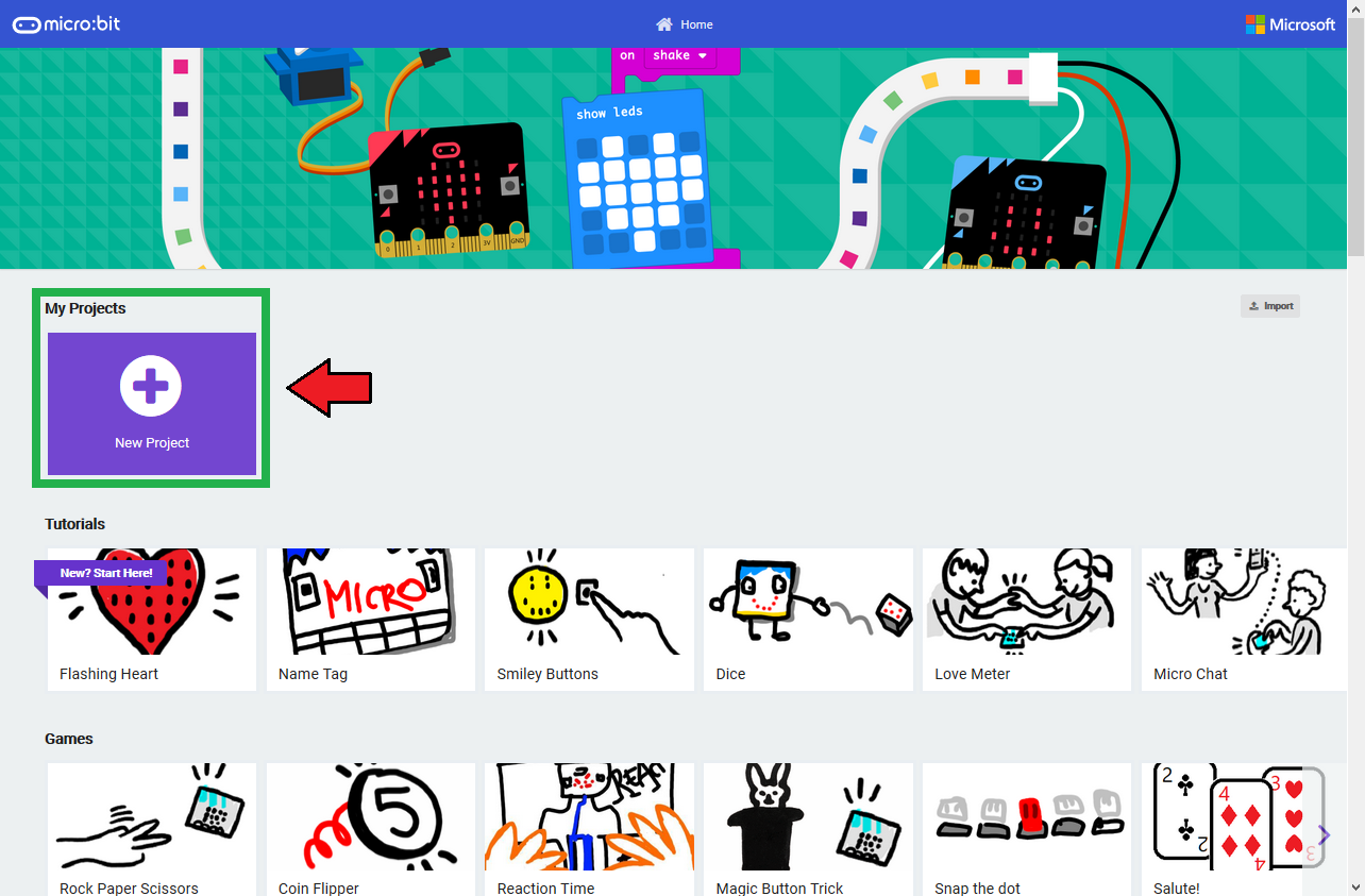
To get started with using MakeCode with the miccro:bit, head over to the MakeCode for micro:bit website by Microsoft. Then, click the New Project button to start a new project and open the Editor. (*Yes, all you only need to get start coding is a computer with internet access, an up-to-date web browser, and an available USB port!)
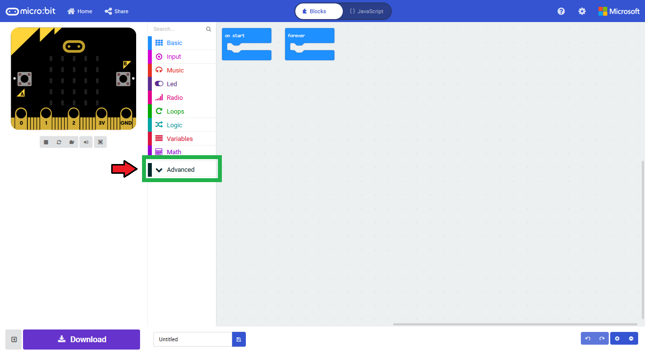
Once you have the editor up, click on the the Advanced block in the block library to reveal the drop down menu.
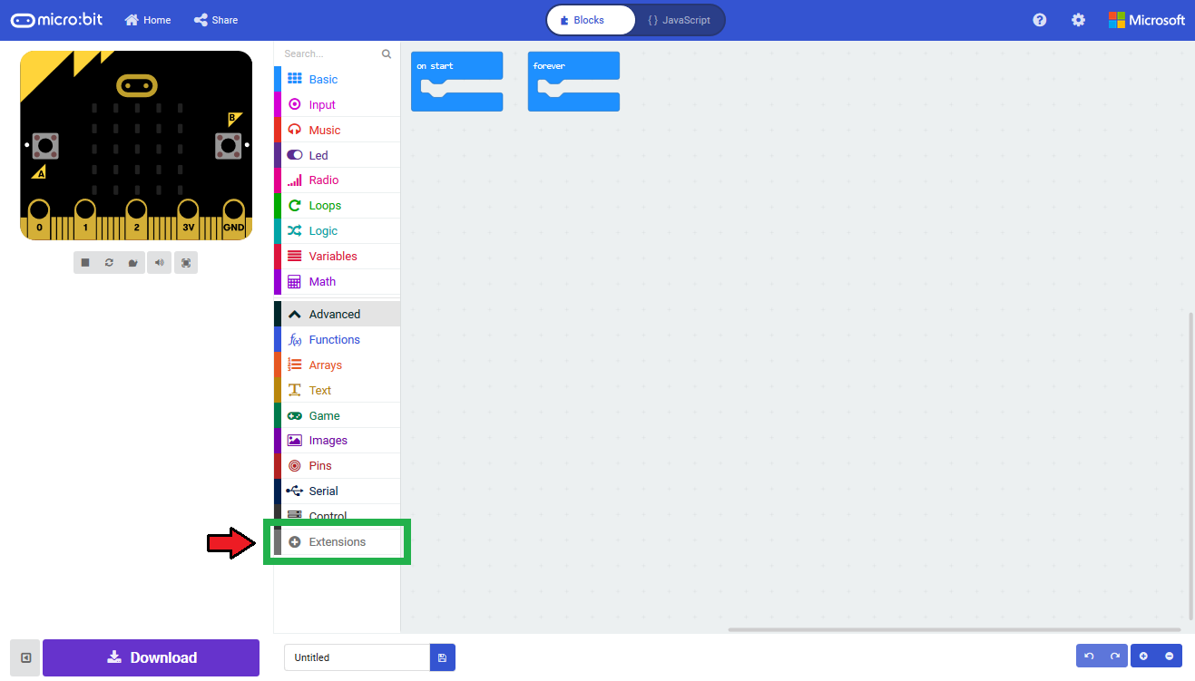
Finally, click on the Extensions block. This should bring up the extensions page. (*Alternatively, you could also click on the extensions link from the settings menu.)
There are two methods for finding the gator:RTC extension:
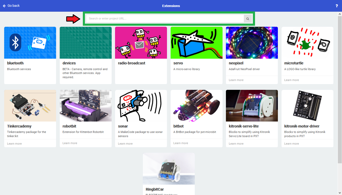
Search for the gator:RTC extension using the GitHub repository link to the pxt-package:
https://github.com/sparkfun/pxt-gator-RTC
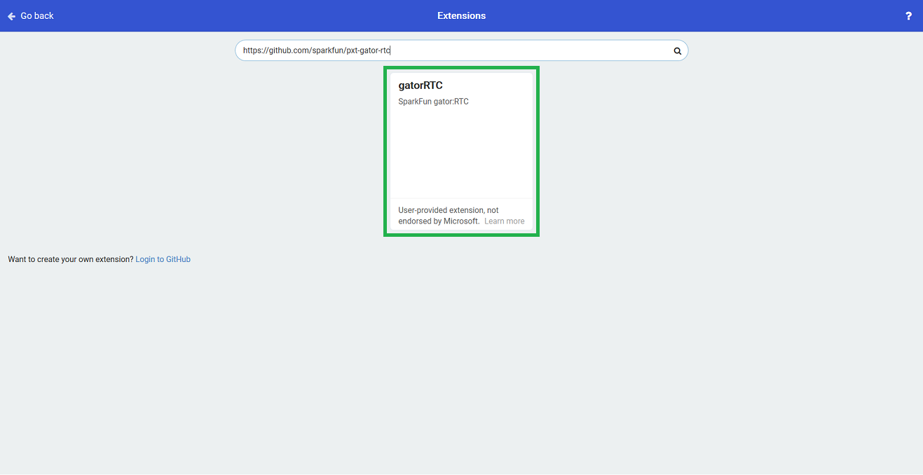
Then, click on the box for the extension to add it to the block library. The gator:RTC extension should now appear in the block library.

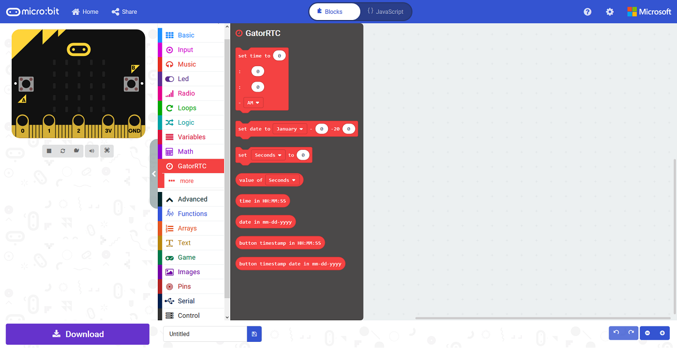
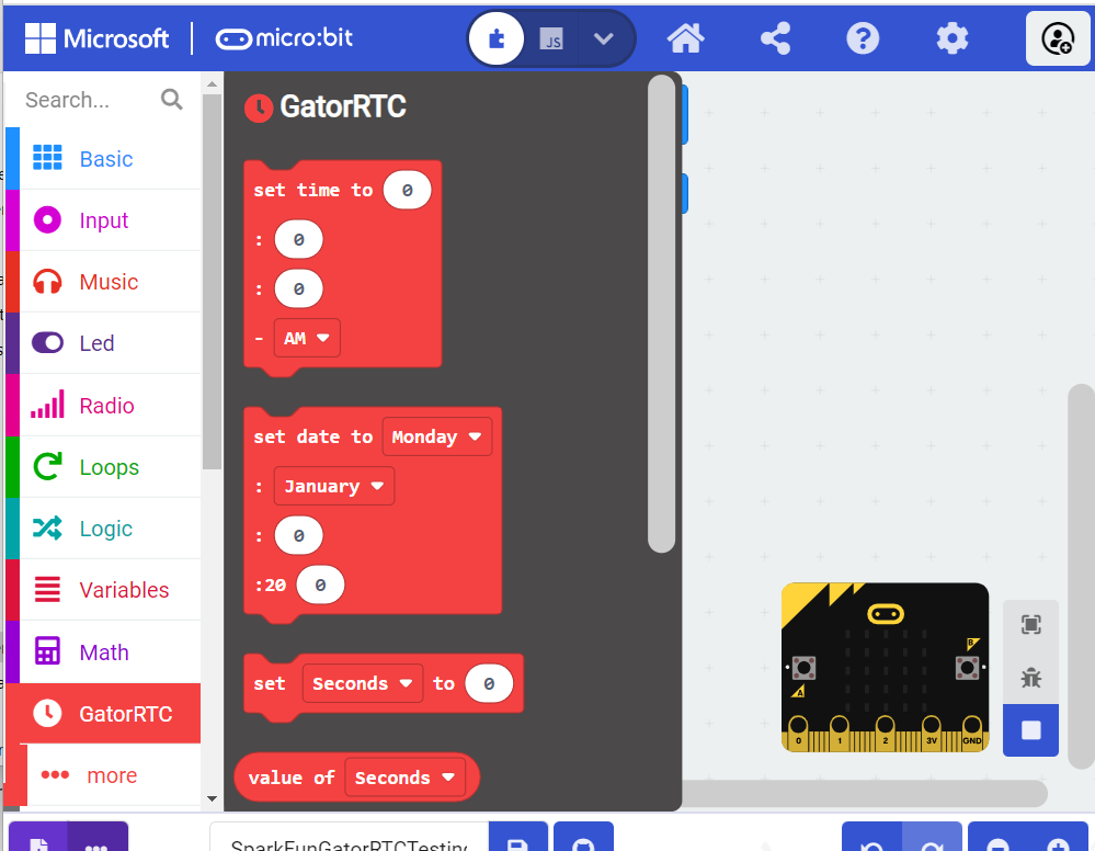
To verify that you have added the extension, click on the gator:RTC block to make sure that your drop down menu options match the image below.
Now that you have added the gator:particle extension to the Editor, lets start with some example code. Plug the micro:bit into your computer using an USB micro-B cable after you have assembled your hardware with the instructions from the previous section. The micro:bit should appear on your computer as a removable storage device.

To upload new code, this is where you will be copying the downloaded .hex file to later.
HH:MM:SS in a 12-hour format. This block doesn't prohibit invalid entries (e.g 13:01:53 AM). Double check the time that is being set is valid; otherwise, the RTC may respond improperly when called upon.
HH- Integer value for the our in 12-hour format (i.e. The 3rd hour after 12 should be entered as 3). There is also a slider that can be easily used.
0 to 12MM- Minutes in integer format (i.e. The 20th minute past the hour should be entered as 20). There is also a slider that can be easily used.
0 to 59SS- Seconds in integer format (i.e. The 30th second past the minute should be entered as 20). There is also a slider that can be easily used.
0 to 5912-Hour Period- Drop down menu to select the 12-hour period.
AM- Ante meridiem (i.e. before noon).PM- Post meridiem (i.e. after noon).Weekday, Month - DD - 20YY. This block doesn't prohibit invalid entries (e.g Feb 29th for leap years, Sept. 31st, or YY = 100). Double check the date that is being set is valid; otherwise, the RTC may respond improperly when called upon.
Weekday- Drop down menu to select the weekday.
MondayTuesdayWednesdayThursdayFridaySaturdaySundayMonth- Drop down menu to select the month.
JanuaryFebruaryMarchAprilMayJuneJulyAugustSeptemberOctoberNovemberDecemberDD- Day in integer format (i.e. The 3rd should be entered as 3). There is also a slider that can be easily used.
0 to 31YY- Year in integer format (i.e. The 2019 should be entered as 19). (The calender is only leap-year accurate for the years 2000 to 2099.)
0 to 99set _____ to ___
This block should allows users to change a specific component of time. This block doesn't prohibit invalid entries. Double check the that the modification is valid; otherwise, the RTC may respond improperly when called upon.
Unit of Time- Drop down menu to select the unit of time you want to change.
SecondsMinutesHoursDateMonthYearWeekdayValue- Value in integer format.
Seconds- Input an integer:
0 to 59Minutes- Input an integer:
0 to 59Hours- Input an integer:
0 to 12 (if in 12-hour format)0 to 24 (if in 24-hour format)Date- Input an integer:
0 to 31Month- Input an integer:
0 to 12Year- Input an integer:
0 to 99Weekday- Input an integer:
0- Monday1- Tuesday2- Wednesday3- Thursday4- Friday5- Saturday6- Sundayvalue of _____
This is a value block that returns the value for the stored component of time from the RTC.
Unit of Time- Drop down menu to select the unit of time you want to retrieve.
Seconds- Returns an integer:
0 to 59Minutes- Returns an integer:
0 to 59Hours- Returns an integer:
0 to 12 (if in 12-hour format)0 to 24 (if in 24-hour format)Date- Returns an integer:
0 to 31Month- Returns an integer:
0 to 12Year- Returns an integer:
0 to 99Weekday- Returns an integer:
0- Monday1- Tuesday2- Wednesday3- Thursday4- Friday5- Saturday6- Sundaytext of weekday
This is a value block that returns a string for the weekday.
time in HH:MM:SS
This is a value block that returns a string for the time stored by the RTC in a HH:MM:SS format.
date in mm-dd-yyyy
This is a value block that returns a string for the date stored by the RTC in a mm-dd-yyyy format.
button timestamp in HH:MM:SS
This is a value block that returns a string for the previous time, marked by the RTC timestamp button in a HH:MM:SS format.
button timestamp in mm-dd-yyyy
This is a value block that returns a string for the previous date, marked by the RTC timestamp button in a mm-dd-yyyy format.
set time to ___:___:___ in 24 hour mode
This block allows users to set the time stored in the RTC. The time should take the following format: HH:MM:SS in a 24-hour format. This block doesn't prohibit invalid entries (e.g 25:01:53). Double check the time that is being set is valid; otherwise, the RTC may respond improperly when called upon.
HH- Integer value for the our in 24-hour format (i.e. The 3rd hour after midnight should be entered as 3). There is also a slider that can be easily used.
0 to 24MM- Minutes in integer format (i.e. The 20th minute past the hour should be entered as 20). There is also a slider that can be easily used.
0 to 59SS- Seconds in integer format (i.e. The 30th second past the minute should be entered as 20). There is also a slider that can be easily used.
0 to 59time in yyyy-mm-ddThh:mm:ss
This is a value block returns a string for the time stored by the RTC in ISO8601 format.
date in dd-mm-yyyy
This is a value block that returns a string for the date stored in the RTC in dd-mm-yyyy format.
button timestamp in yyyy-mm-ddThh:mm:ss
This is a value block returns a string for the previous time, marked by the RTC timestamp button in ISO8601 format.
button timestamp in dd-mm-yyyy
This is a value block returns a string for the previous time, marked by the RTC timestamp button in dd-mm-yyyy format.
value of button timestamp in _____
This is a value block that returns a specific component of timestamp stored by the RTC.
Unit of Time- Drop down menu to select the unit of time you want to retrieve from timestamp.
Seconds- Returns an integer:
0 to 59Minutes- Returns an integer:
0 to 59Hours- Returns an integer:
0 to 24 (in 24-hour format)Date- Returns an integer:
0 to 31Month- Returns an integer:
0 to 12Year- Returns an integer:
0 to 99set to _____ time
This block allows users to change the time format between a 12-hour and 24-hour.
Standard- Changes the time to a 12-hour format.Military- Changes the time to a 24-hour format.Below, is a simple example of how to take simple readings from the RTC. To use this example, there are multiple options for accessing the .hex file:
.hex file..hex file..hex file..hex file from the button below or the link on the bottom of the display.The output is redirected over the serial port to avoid conflicts on pins P0 and P1, which are also used for serial communication. To read the sensor values, pull up your favorite serial terminal emulator. Then, connect to the serial port that the micro:bit is on; the default baud rate is 115200 bps. Below, is an example of an output of the time stored by the gator:RTC using the example code.
In the read out from the RTC, you can see with the 1.5 and 0.8 second delays that the resolution of the RTC is limited to one second intervals. (Between the change from a 1.5 to a 0.8 delay, the seconds value was reset back to 0 seconds.) Additionally, you should note the various subtleties in timing formats for the functions used.
If you are confused to how the timestamp button works, the read out in the forever loop prints out both the current time and the timestamp of the last button press. In the example readings, you can see the timestamp change from a few button presses.
<
div class="alert alert-info" role="alert">
Extension not working?
This product's extension has a dependency on Microsoft's build process. If the usual method of installing the MakeCode extension gives an error, you will need to manually install the MakeCode extension. We have provided a local build of this extension that can be uploaded to MakeCode:
To manually install this extension in makecode, go to the "Extensions" tab on the left side of the makecode site:
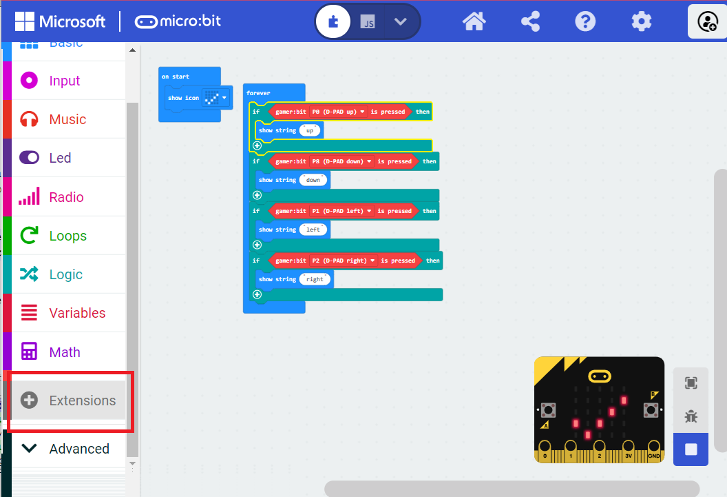
In the location you'd normally search for an extension, you'll notice an upload button on the right:
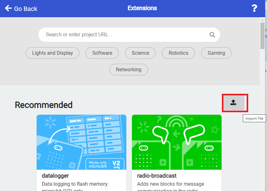
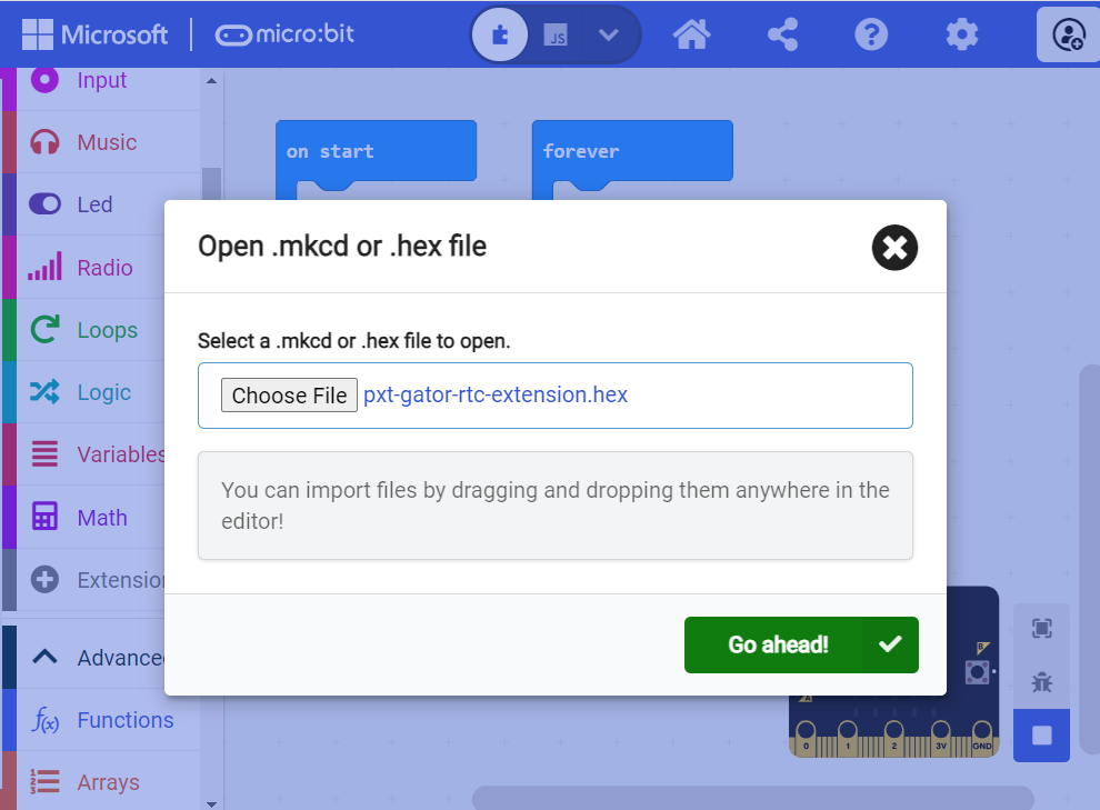
Click on this, and you'll get a window allowing you to upload your own built extension. Navigate to where you saved the above extension hex, and upload it to your project.
You should be able to see the extension and its functions now. In addition, you'll be able to build and download your project to your variant of micro:bit.
Check that your power and data connections are correct and that the power VOUT switch is in the ON position on the gator:bit (v2).
The RTC only reports the time down to 1 second intervals and cannot return fractions of a second. It will report the lower value between seconds until the next second is hit (e.g. at 15.6 seconds past the minute is will report 15 seconds until the the 16th second is reached).
For more product information, check out the resources below:
Interested in the micro:bit? Check out some of these other micro:bit products:
Need some inspiration for your next project? Check out some of these other micro:bit product tutorials:
learn.sparkfun.com | CC BY-SA 3.0 | SparkFun Electronics | Niwot, Colorado