Qwiic Real Time Clock Module (RV-1805) Hookup Guide
 Englandsaurus
 Introduction
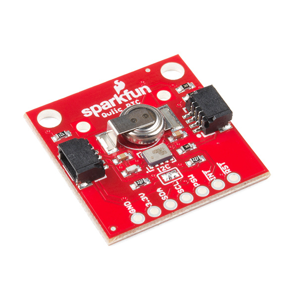
The Qwiic Real Time Clock (RTC) module is a Qwiic-enabled breakout board for the RV-1805 module! The RTC is ultra-low power (running at about 22 nA in its lowest power setting) so it can use a supercapacitor for backup power instead of a normal battery. This means infinite charge and discharge cycles without any degradation to the "battery" (in this case, a supercapacitor). The breakout board is also a part of SparkFun's Qwiic system, so you won't have to do any soldering to figure out what time it is.
In this hookup guide, we'll take advantage of the Arduino IDE to automatically set the time of the RTC to the compiler time. Once we have the time set, we'll set the alarm to a time of our choice and have it generate a signal on the interrupt pin. We'll also look at how charged the RTC is so we know when to unplug the RTC from power (when it's full of course). Finally, we'll look at how to store other data into the RTC so we can keep important variables safe when our system loses power. We'll also go over how to extend the battery life of your RTC by adding an external battery.
Required Materials
To get started, you'll need a microcontroller to control everything in your project.

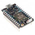
Particle Photon (Headers)
WRL-13774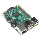
Raspberry Pi 3
DEV-13825Now to get your microcontroller into the Qwiic ecosystem, the key will be one of the following Qwiic shields to match your preference of microcontroller:

SparkFun Qwiic Shield for Photon
DEV-14477You will also need a Qwiic cable to connect the shield to your RTC, choose a length that suits your needs.

Qwiic Cable - 50mm
PRT-14426
Qwiic Cable - 100mm
PRT-14427
Qwiic Cable - 200mm
PRT-14428
Qwiic Cable - 500mm
PRT-14429Finally, if your application requires that your RTC be without power for over a month, we'd recommend using the optional battery and battery holder to extend the time that the RTC will remain active without power.

Suggested Reading
If you aren't familiar with the Qwiic system, we recommend reading here for an overview.
| Qwiic Connect System |
We would also recommend taking a look at the hookup guide for the Qwiic Shield if you haven't already. Brushing up on your skills in I2C is also recommended, as all Qwiic sensors are I2C.
How to Solder: Through-Hole Soldering
I2C
Qwiic Shield for Arduino & Photon Hookup Guide
Hardware Overview
Let's look over a few characteristics of the RV-1805 RTC so we know a bit more about how it behaves.
| Characteristic | Range |
|---|---|
| Operating Voltage (Startup) | 1.6V - 3.6V |
| Operating Voltage (Timekeeping) | 1.5V - 3.6V |
| Operating Temperature | -40°C - 85°C |
| Time Accuracy | ±2.0 ppm |
| Current Consumption | 22 nA (Typ.) |
| I2C Address | 0x69 |
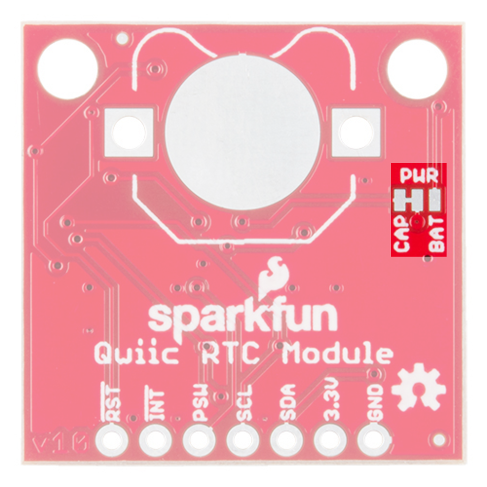
Pins
The characteristics of the available pins on the RTC are outlined in the table below.
| Pin Label | Pin Function | Input/Output | Notes |
|---|---|---|---|
| 3.3V | Power Supply | Input | Should be between 1.95 - 3.6V |
| GND | Ground | Input | 0V/common voltage. |
| SDA | I2C Data Signal | Bi-directional | Bi-directional data line. Voltage should not exceed power supply (e.g. 3.3V). |
| SCL | I2C Clock Signal | Input | Master-controlled clock signal. Voltage should not exceed power supply (e.g. 3.3V). |
| PSW | Power Switch | Output | Power Switch pin, digital output. Capable of switching power on an external microcontroller. |
| INT | Interrupt | Output | Interrupt pin, active low, digital output. Also configurable as a square wave up to 32.768 kHz |
| RST | Reset | Output | Reset pin, active low, digital output |
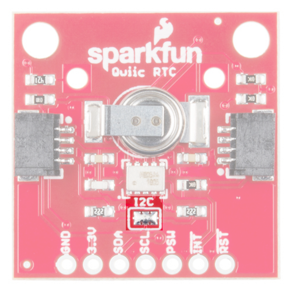
Optional Features
The Qwiic RTC has onboard I2C pull-up resistors; if multiple sensors are connected to the bus with the pull-up resistors enabled, the parallel equivalent resistance will create too strong of a pull-up for the bus to operate correctly. As a general rule of thumb, disable all but one pair of pull-up resistors if multiple devices are connected to the bus. If you need to disconnect the pull up resistors they can be removed by removing the solder on the corresponding jumpers highlighted below.
There is also the option to add a battery to the board if the supercapacitor just isn't gonna keep your project powered long enough (keep in mind, the supercap can hypothetically make the board keep time for around 35 days) you can solder on an external battery. Keep in mind that if doing so, you'll need to cut the trace connecting power to the capacitor, and add solder to the side of the jumper that connects power to the battery labeled as BAT.
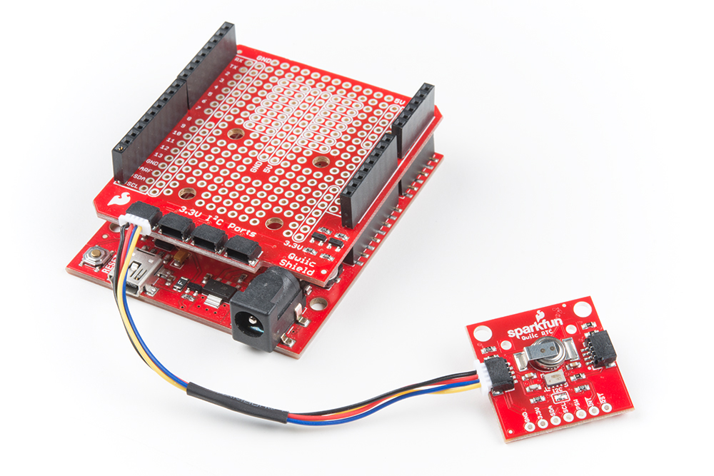
Hardware Assembly
If you haven't yet assembled your Qwiic Shield, now would be the time to head on over to that tutorial.
With the shield assembled, Sparkfun's new Qwiic environment means that connecting the sensor could not be easier. Just plug one end of the Qwiic cable into the RTC breakout, the other into the Qwiic Shield of your choice. You'll be ready to upload a sketch and start keeping track of the time. It seems like it's too easy too use, but that's why we made it that way!
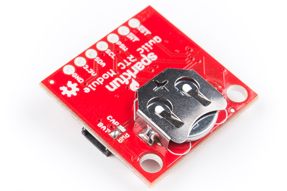
External Coin Cell Battery
Now if you've decided that you'd like to power the RTC from a battery instead of a supercapacitor, you'll need to cut the trace jumper on the back of the board to disconnect power from the supercapacitor. Add solder to the other side of the jumper to connect power to the battery. Once you've done this, add a little bit of solder on the circular pad for contact, solder the battery holder legs to the board, insert the battery, and you're good to go!
Library Overview
Note: This example assumes you are using the latest version of the Arduino IDE on your desktop. If this is your first time using Arduino, please review our tutorial on installing the Arduino IDE. If you have not previously installed an Arduino library, please check out our installation guide.
Before we get into programming our RTC, let's download and check out the available functions in our library. SparkFun has written a library to control the Qwiic RTC. You can obtain these libraries through the Arduino Library Manager. Search for SparkFun Qwiic RTC RV1805 Arduino Library to install the latest version. If you prefer downloading the libraries from the GitHub repository and manually installing it, you can grab them here:
Let's get started by looking at the functions that set up the RTC.
Setup and Settings
boolean begin( TwoWire &wirePort = Wire );--- The begin function initalizes the RTC, enabling the trickle charging circuit along with low power mode. Also sets the RTC to a 12-hour time format.void reset(void);--- Performs a full software reset on the RTC.bool setToCompilerTime();--- Set's the RTC to the time on the compiler.bool setTime(uint8_t hund, uint8_t sec, uint8_t min, uint8_t hour, uint8_t date, uint8_t month, uint8_t year, uint8_t day);--- Set's the time registers of the RTC to a chosen time using individual variables.bool setTime(uint8_t * time, uint8_t len)--- Set's the time registers of the RTC to a chosen time using an array of times in the following order{Hundredths, Seconds, Minutes, Hours, Date, Month, Year, Day}. Please noteuint8_t lenmust be 7, the length of the time array, for this function to set the time properly.bool setHundredths(uint8_t value);--- Sets the hundredths register tovalue.bool setSeconds(uint8_t value);--- Sets the seconds register tovalue.bool setMinutes(uint8_t value);--- Sets the minutes register tovalue.bool setHours(uint8_t value);--- Sets the hours register tovalue.bool setWeekday(uint8_t value);--- Sets the weekday register tovalue.bool setDate(uint8_t value);--- Sets the date register tovalue.bool setMonth(uint8_t value);--- Sets the month register tovalue.bool setYear(uint8_t value);--- Sets the year register tovalue.void set12Hour();--- Sets the RTC to 12 hour mode.void set24Hour();--- Sets the RTC to 24 hour mode.void enableTrickleCharge(uint8_t diode = DIODE_0_3V, uint8_t rOut = ROUT_3K);--- Connects an internal diode and resistor to enable the trickle charging circuit to charge the supercapacitor. The default values are the fastest for charging the capacitor, although other globally scoped variables (listed below) can be passed to change the value of the diode and resistor using in the charging circuit.DIODE_0_3V--- 0.3V DiodeDIODE_0_6V--- 0.6V DiodeDIODE_DISABLE--- Disconnects diode, disables trickle charging circuitROUT_3K--- 3 kΩ ResistorROUT_6K--- 6 kΩ ResistorROUT_11K--- 11 kΩ ResistorROUT_DISABLE--- Disconnects resistor, disables the trickle charging circuit.
void disableTrickleCharge();--- Disables the trickle charging circuit.void enableLowPower();--- Enables switching to the low power RC oscillator when the RTC is powered by the supercapacitor or battery.
Interrupt Functionality
void enableInterrupt(uint8_t source);--- Enables a given interrupt based on the value ofsource, which can be any of the following.INTERRUPT_EIE--- External InterruptINTERRUPT_AIE--- Alarm InterruptINTERRUPT_TIE--- Timer InterruptINTERRUPT_BLIE--- Battery Interrupt
void disableInterrupt(uint8_t source);--- Disables a given interrupt based on the value ofsource, see above for possible values ofsource.void clearInterrupts();--- Clears all interrupt sources.void setCountdownTimer(uint8_t duration, uint8_t unit, bool repeat = true, bool pulse = true);--- Sets the countdown timer to trigger the interrupt ifINTERRUPT_TIEis enabled.uint8_t duration--- Sets the duration (be aware that this is just a BCD, and the time it takes to increment one LSB is decided byunit).uint8_t unit--- Sets the time resolution of each LSB.0b00:1/4096 s0b01:1/64 s0b10:1 s0b11:60 s
bool repeat--- If repeat is true, the countdown timer will reset when it reaches 0, otherwise, it will stop.bool pulse--- The interrupt will normally be a pulse unless both pulse and repeat are false, in which case the interrupt will be a level until the interrupt flag is cleared manually.
enableSleep()--- Enables SleepsetPowerSwitchFunction(uint8_t function);--- Changes the behavior of the PSW pin.0b000:Inverse of the combined interrupt signal IRQ if at least one interrupt is enabled.0b001:Square wave if SQW = 1;0b010:Reserved.0b011:Inverse of alarm if alarm interrupt is set0b100:Timer if timer interrupt is set0b101:Inverse of timer if timer interrupt is set0b110:SLEEP Signal0b111:Static PSWB bit
setPowerSwitchLock(bool lock)--- Sets the power switch lock, if the lock is enabled, the PSWB bit cannot be set to 1. This is typically used when using PSW as a power switch, as setting PSWB puts PSW in a high impedance state.setsStaticPowerSwitchOutput(bool psw);--- Enables the PSW bit to switch.bool setAlarm(uint8_t sec, uint8_t min, uint8_t hour, uint8_t date, uint8_t month);--- Sets the alarm to a chosen time using individual variables.bool setAlarm(uint8_t * time, uint8_t len);--- Sets the alarm to a chosen time using an array of times.uint8_t lenmust be 7, the length of the time array, for this function to set the alarm properly.enableAlarmInterrupt();--- Attaches the interrupt pin to the alarm function.void setAlarmMode(uint8_t mode);---modemust be between 0 and 7, alarm goes off with match of second, minute, hour, etc depending on the value ofmode.0: Disabled1: Hundredths, seconds, minutes, hours, date and month match (once per year)2: Hundredths, seconds, minutes, hours and date match (once per month)3: Hundredths, seconds, minutes, hours and weekday match (once per week)4: Hundredths, seconds, minutes and hours match (once per day)5: Hundredths, seconds and minutes match (once per hour)6: Hundredths and seconds match (once per minute)7: Depends on the alarm value for hundredths.0-99: Hundredths match (once per second)240-249: Once per tenth (10 Hz)255: Once per hundredth (100 Hz)
void enableBatteryInterrupt(uint8_t voltage, bool edgeTrigger);--- Enables the battery interrupt and sets the voltage at which the interrupt is triggered. The trigger voltages for different values ofvoltageandedgeTriggerare found in the table below.
| Voltage | EdgeTrigger = true | EdgeTrigger = false |
|---|---|---|
| 0 | 3.0V | 2.5V |
| 1 | 2.5V | 2.1V |
| 2 | 2.2V | 1.8V |
| 3 | 1.6V | 1.4V |
void setReferenceVoltage(uint8_t voltage, bool edgeTrigger);--- Can be used to set the reference voltage used for the battery interrupt. Use the values in the above table.bool checkBattery(uint8_t voltage, bool edgeTrigger);--- Checks if the battery level is above the threshold set by the valuesvoltageandedgeTrigger.
Reading the RTC
bool updateTime();--- Updates the local time array with the RTC time registers.stringDateUSA();--- Returns the date in MM-DD-YYYY format.stringDate();--- Return date in DD-MM-YYYY format.stringTime();--- Return time in HH:MM:SS with AM/PM if the RTC is in 12 hour mode.uint8_t getHundredths();--- Returns the value of the hundredths register.uint8_t getSeconds();--- Returns the value of the seconds register.uint8_t getMinutes();--- Returns the value of the minutes register.uint8_t getHours();--- Returns the value of the hours register.uint8_t getWeekday();--- Returns the value of the weekday register.uint8_t getDate();--- Returns the value of the date register.uint8_t getMonth();--- Returns the value of the month register.uint8_t getYear();--- Returns the value of the year register.bool is12Hour();--- Returns true if 12hour bit is set.bool isPM();--- Returns true ifis12Hour() == trueand PM bit is set.uint8_t status();--- Returns the status byte.uint8_t BCDtoDEC(uint8_t val);--- Converts from BCD to decimal format.uint8_t DECtoBCD(uint8_t val);--- Converts from decimal to BCD format.uint8_t readRegister(uint8_t addr);--- Reads the register ataddr.bool writeRegister(uint8_t addr, uint8_t val);--- Writesvalto locationaddr.bool readMultipleRegisters(uint8_t addr, uint8_t * dest, uint8_t len);--- Readslennumber of registers, incrementing up from theaddrlocation, into the arraydest.bool writeMultipleRegisters(uint8_t addr, uint8_t * values, uint8_t len);--- Writeslennumber of registers, incrementing up from theaddrlocation, from the arrayvalues.
Example Code
Example 1 - Set Time
Once you've installed the SparkFun Qwiic RTC RV-1805 Arduino library go to File > Examples > SparkFun Qwiic RTC RV-1805 Arduino Library > Example1-Set_Time to open the example sketch. We will use this first sketch to set up our RTC's internal clock. Take note of the following lines of code, which use the compiler time to set the RTC's clock.
language:c
if (rtc.setToCompilerTime() == false) {
  Serial.println("Something went wrong setting the time");
}
Note that this doesn't reset every time we upload code into our Arduino, so make sure you restart the IDE before uploading to get the most current time to upload into your RTC.
Example 2 - Print Time
Now that we've set the time on the RTC, let's read it out. Open the next example by heading to File > Examples > SparkFun Qwiic RTC RV-1805 Arduino Library > Example2-Print_Time to open the example sketch. After initializing the RTC object, we attempt to update the time variables in our microcontroller with the values from the RTC using some of the code below. If this is successful, we print them out.
language:c
if (rtc.updateTime() == false) //Updates the time variables from RTC
  {
    Serial.print("RTC failed to update");
  }
Also, in its need to feel special, the United States formats its dates differently than the rest of the world (We do MM/DD/YYYY format while everybody else does DD/MM/YYYY format). So if you don't live in the U.S. or you just like how the rest of the world formats their dates, you'll need to uncomment the following line of code (line 50) in your sketch.
language:c
//String currentDate = rtc.stringDate());
Once you upload this code to your microcontroller, go ahead and open the serial monitor with a baud rate of 9600. You should see the current date and time go streaming past, looking something like the image below.
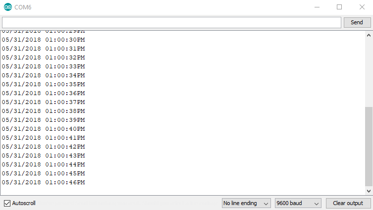
If your output is showing the incorrect time, you may need to recompile your sketch to get the latest compiler time using the code from the first example. If this doesn't work, try restarting the Arduino IDE to get a new compiler time.
Example 3 - Trickle Charging
To pull up the next example, go to File > Examples > SparkFun Qwiic RTC RV-1805 Arduino Library > Example3-Trickle_Charging. This example will show us how to fiddle with the RTC's trickle charging circuit to configure it for different charge rates as well as disable it if we want to use a coin cell battery.
The trickle charge circuit consists of a diode (0.3v or 0.6v drop) in series with a resistor (3kOhm, 6kOhm, or 11kOhm) These are available to pass into the function as DIODE_0_3V, DIODE_0_6V, ROUT_3K, ROUT_6K, ROUT_11K. The fastest possible rate, with a 0.3V diode and 3kOhm resistor is enabled by default. Note that the trickle charger should only be used for charging the supercapacitor. Disable the trickle charger simply by calling disableTrickleCharge() if you've connected the optional battery.
Example 4 - Alarm Interrupt
To pull up the next example, go to File > Examples > SparkFun Qwiic RTC RV-1805 Arduino Library > Example4-Alarm_Interrupt. This example shows how to enable and use the alarm interrupt to generate an interrupt every time some or all of the alarm registers match the time register. First, we need to set up what time we want the alarm to go off. To do this, we set the variables in the preamble to the time we would like. They default to the values below as these are the default alarm values.
language:c
byte secondsAlarm = 0;
byte minuteAlarm = 0;
byte hourAlarm = 0;
byte dateAlarm = 0;
byte monthAlarm = 0;
Next, we need to set which parts of the time must match in order for the alarm to be triggered. to do this, we use the setAlarmMode(uint8_t mode); where mode is a number between 0 and 7. Go to line 60 (in the setup loop) if you'd like to change how often the alarm is triggered. The values corresponding to which registers much match are listed below.
0: Disabled1: Hundredths, seconds, minutes, hours, date and month match (once per year)2: Hundredths, seconds, minutes, hours and date match (once per month)3: Hundredths, seconds, minutes, hours and weekday match (once per week)4: Hundredths, seconds, minutes and hours match (once per day)5: Hundredths, seconds and minutes match (once per hour)6: Hundredths and seconds match (once per minute)7: Depends on the alarm value for hundredths.0-99: Hundredths match (once per second)240-249: Once per tenth (10 Hz)255: Once per hundredth (100 Hz)
Once you've set the alarm to your liking, go ahead and upload the code to your microcontroller. The interrupt pin will now drop low every time the alarm is triggered. If you don't want to physically check the status of the interrupt pin, you can uncomment the section of code in the void loop that reads the status register of the RTC. This will alert you when the alarm has been triggered.
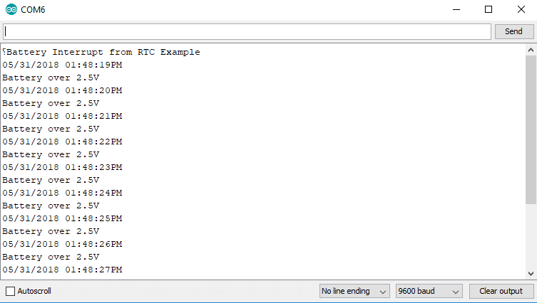
Example 5 - Battery Interrupt
To pull up the next example, go to File > Examples > SparkFun Qwiic RTC RV-1805 Arduino Library > Example5-Battery_Interrupt to open the example sketch. This example checks the charge level of the supercapacitor and alerts the user when it has reached 2.5V. You can change the voltage level at which the user is alerted by changing the values passed into checkBattery(voltage, edgeTrigger);. Follow the chart on the Library Overview page to select the proper voltage. Once you've uploaded the example code to your microcontroller, go ahead and open the serial monitor to 9600 baud. The output should look something like the image below once the RTC is charged to the selected voltage.
Resources and Going Further
Now that you've successfully got your Qwiic RTC (RV-1805) module up and running, it's time to incorporate it into your own project!
For more information about the Qwiic RTC (RV-1805) module, check out the resources below:
Need some inspiration for your next project? Check out some of these related tutorials:
MetaWatch Teardown and Arduino Hookup
Experiment Guide for the Johnny-Five Inventor's Kit
Real Time Clock Module - RV-8803 (Qwiic) Hookup Guide
SparkFun Clock Generator 5P49V60 (Qwiic) Hookup Guide
Or check out some of these blog posts for ideas: