SparkFun Edge Hookup Guide
 Liquid Soulder
 Hardware Hookup
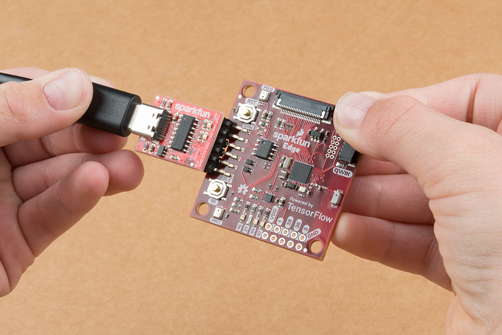
It's very easy to get started using the Edge board - all you need to do is provide power! Right off the bat you can try out the AI voice recognition by seeing the yellow LED light up for 'Yes' and the red LED light up for 'No.'
Power + Programming
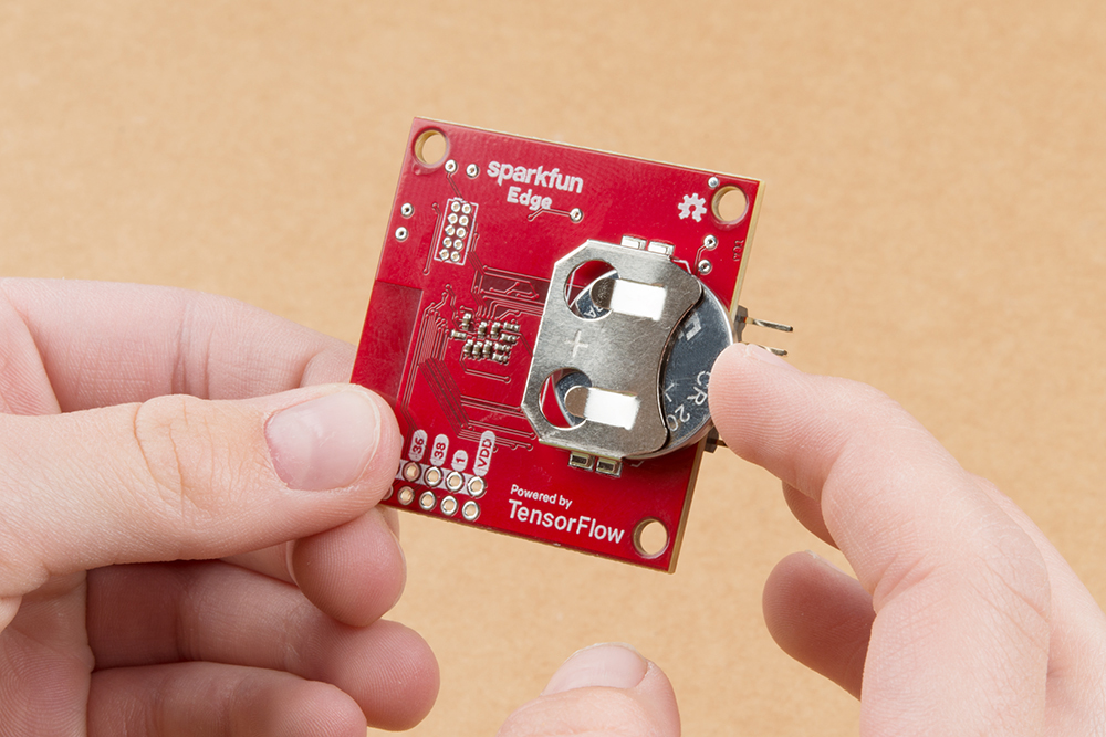
To power the board either place a charged CR2031 3V battery into the coin cell holder or plug in your USB-serial converter.
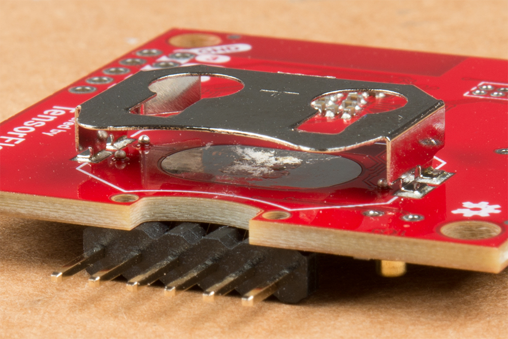
If you want to upload new code or see what the Edge board has to say to you then you'll need to be able to read the UART pins which are broken out just above the coin cell holder. The pinout is compatible with SparkFun serial breakouts like the Serial Basic Breakout or the new Serial Basic Breakout with USB C. The ability to toggle the DTR line from USB is required for bootloading.
With your chosen method of connection at hand begin making the connections with care. If you have USB-serial bridge with the compatible pinout (order DTR, RXI, TXO, VCC, CTS, GND from the perspective of the bridge) you can simply make sure that the GRN and BLK labels match up between the bridge and the Edge board. If you are using some other way to view/send UART data then make sure to connect the TX of the bridge to the RX of the Edge and vice-versa. Also make sure to connect GND (closest to the BLK label on the Edge) and DTR (closest to the GRN label) pins. From the bridge's perspective RXI is next to DTR and TXO is next to RXI.
Camera
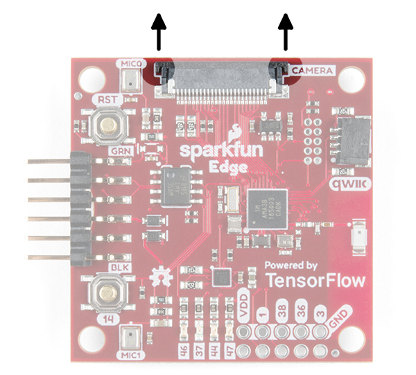
To connect the camera, you'll need to carefully slide the flexible ribbon cable connector's locking tab out. The locking tab slides out parallel to the board so you'll need to push each side of the tab with your fingernails. The image below highlights where you would need to place your fingernails to slide the tab out.
Once the locking tab is out, you can insert the camera connector into the slot. Face the camera's exposed contacts toward the PCB in order to make a connection with the connector's pins. Then insert the cable until it is firmly into the connector. Care must be taken to ensure that the ribbon cable does not have any sharp bends when installing the camera.

When ready, carefully slide the tab back into the locking position using your fingernails.

Your camera should look similar to the images below.
 |
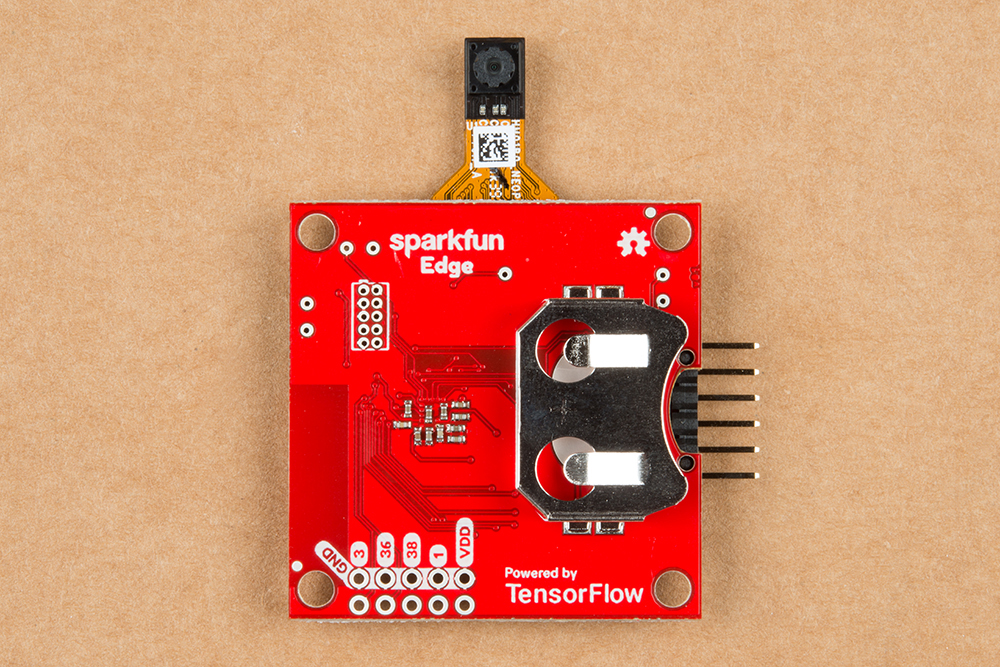 |
| Top View of Edge with Camera | Bottom View of Edge with Camera |
Extensions
With the Edge boards you can add additional I2C sensors with the Qwiic connector and have access to four GPIO pins.
Connecting Qwiic sensors is as simple as chaining them together with Qwiic Cables and then linking that chain to the Edge board. Note, if you have many sensors (5 or more is a good rule of thumb) then you'll need to disconnect the I2C pullup resistors from a few of the boards.
The four available GPIO pins are pads 1, 3, 36, and 38 of the Apollo3. In addition to GPIO functionality some have additional special functions:
| Apollo3 Pad | Special Functions |
|---|---|
| 1 | UART0 TX |
| 3 | ADC Trigger1 |
| 36 | ADC Trigger1, UART1 RX, UART1 CTS, UART0 CTS, PDM Microphone DATA, 32 kHz Clock Output |
| 38 | ADC Trigger3, UART0 CTS, UART1 RX |