SparkFun Clock Generator 5P49V60 (Qwiic) Hookup Guide
Introduction
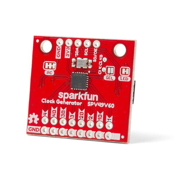
The SparkFun Clock Generator 5P49V60 breakout board offers a wide range of customizable frequencies in a wide range of different signal types using a single reference clock. Four (single output) clock outputs can generate frequencies from 1MHz-200MHz and eight (differential output) clock outputs can generate frequencies from 1MHz-350MHz. The frequency's many properties can be manipulated in code via I2C using the SparkFun Arduino Library. The SparkFun Clock Generator also has four banks of programmable memory for the time when it's ready to sit on its' own within the project without a microcontroller. This hookup guide will go over all of the many available functions of the SparkFun Clock Generator and gives the hardware rundown on what exactly is on this board.
Required Materials
To follow along with this tutorial, you will need the following materials. You may not need everything though depending on what you have. For example, I chose the RedBoard Qwiic as a simple demo, but you could use any microcontroller. Add it to your cart, read through the guide, and adjust the cart as necessary.
Required Tools
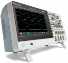
An oscilloscope is highly recommended to verify that the programmed clock signal is correct as its the only way to verify the output accurately. SparkFun only has a few oscilloscopes in its' catalog, but if it's time to add this essential Electrical Engineering tool to your work bench, then check out SparkFun's offerings below. You will also need to have a soldering iron to connect to the clock output pins!
SparkFun Beginner Tool Kit
TOL-14681
Digital Storage Oscilloscope - 100MHz (TBS2104)
TOL-14925Suggested Reading
If you aren't familiar with the Qwiic system, we recommend reading here for an overview.
 |
| Qwiic Connect System |
We would also recommend taking a look at the following tutorials if you aren't familiar with them. In particular the tutorial on how to use an oscilloscopes might be very helpful depending on your experience.


