SparkFun Clock Generator 5P49V60 (Qwiic) Hookup Guide
 Elias The Sparkiest
Hardware Hookup
The Qwiic connector system makes it easy to connect to the clock generator to the RedBoard Qwiic, but to see the output on our SparkFun Clock Generator, it will need to be hooked up to an oscilloscope. To do that, we'll first solder female header pins. Should you decide to use the board without a microcontroller, you will need solder pins or wires to GND and 3V3 pins.

We'll be using LVPECL mode as our output type. Under the Hardware Overview it's mentioned that properly terminating your output depends on its OUTPUT mode. To terminate this properly, we'll use two sets of 100Ω resistors. Placing each set in parallel will result in 50Ω termination to ground.
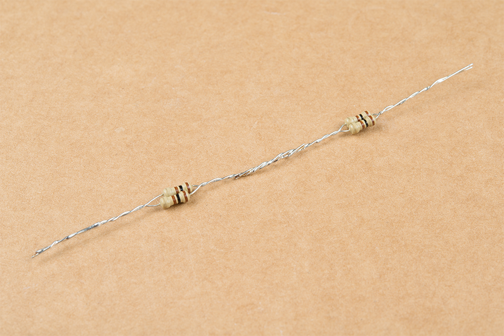
The 50Ω termination will be plugged into the Clock One Output and GND as shown below.

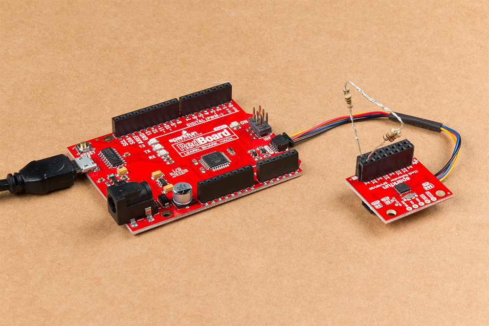
Next, the SparkFun Clock Generator is plugged into the RedBoard Qwiic via the Qwiic cable.
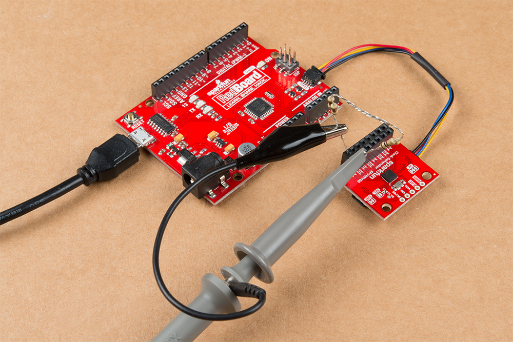
Now the oscilloscope is attached to the terminations as shown below.
Now if you load up Example 1: Generate a Clock Signal you'll see 16MHz output on the oscilloscope's screen.
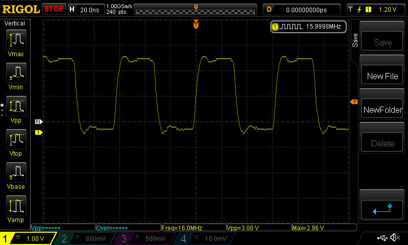
You may notice a bit of over shooting in the picture above and a bit of ringing in the signal. There are a number of reasons why this is happening. I'm terminating my signal on a 1MΩ oscilloscope probe, when I should be using a 50Ω instead. I also have an extended ground cable on the probe, which should be shortened for better signal capture. None the less, I hope that this is still demonstrative of the SparkFun Clock Generator capabilities.