Soil Moisture Sensor Hookup Guide
 Sarah Al-Mutlaq,
  Joel_E_B, Ell C
Hardware Overview and Assembly
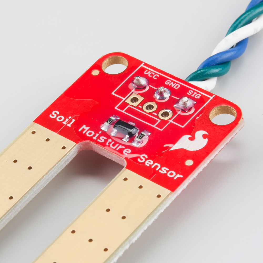
Our original Soil Moisture Sensor is pretty straightforward when it comes to hookup. There are only three pins to connect: VCC, GND, and SIG.
You need to supply power to VCC and GND. We recommend not powering the sensor constantly to prevent corrosion of the probes (more on this in a bit). SIG provides an analog signal out that can be attached to the ADC pin on any microcontroller. The value read on SIG will vary depending on the voltage with which you power the sensor.
Qwiic Enabled Soil Moisture Sensor
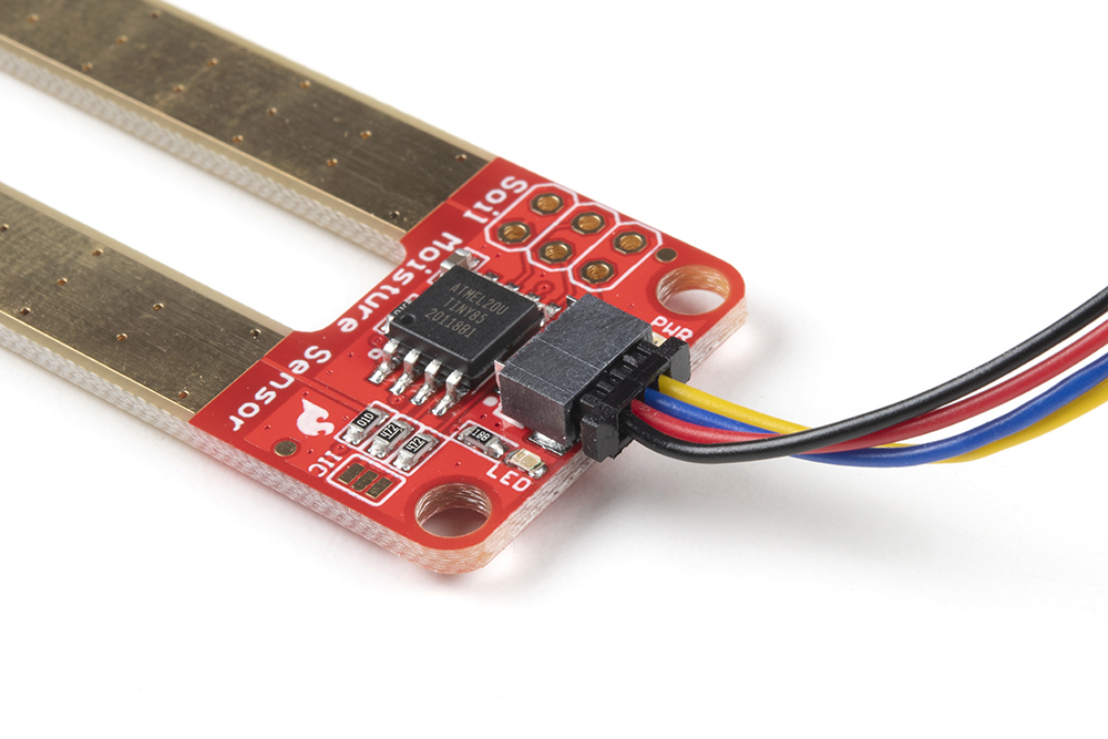
Our Qwiic Soil Moisture Sensor utilizes the I2C protocol with the existing signals and the ATtiny85 MCU as the I2C gateway, which does all the nitty gritty stuff for you. The default I2C address is 0x28. The Qwiic connector should be self-evident, and this board also has pins broken out for SPI programming.
Note: Like our other Qwiic boards, the Qwiic Soil Moisture Sensor comes equipped with pull-up resistors for normal operation. If you are running multiple Qwiic devices on the same circuit, you will want to disable the pull up resistors by using an X-acto knife to cut the joint between the highlighted I2C jumper pads.
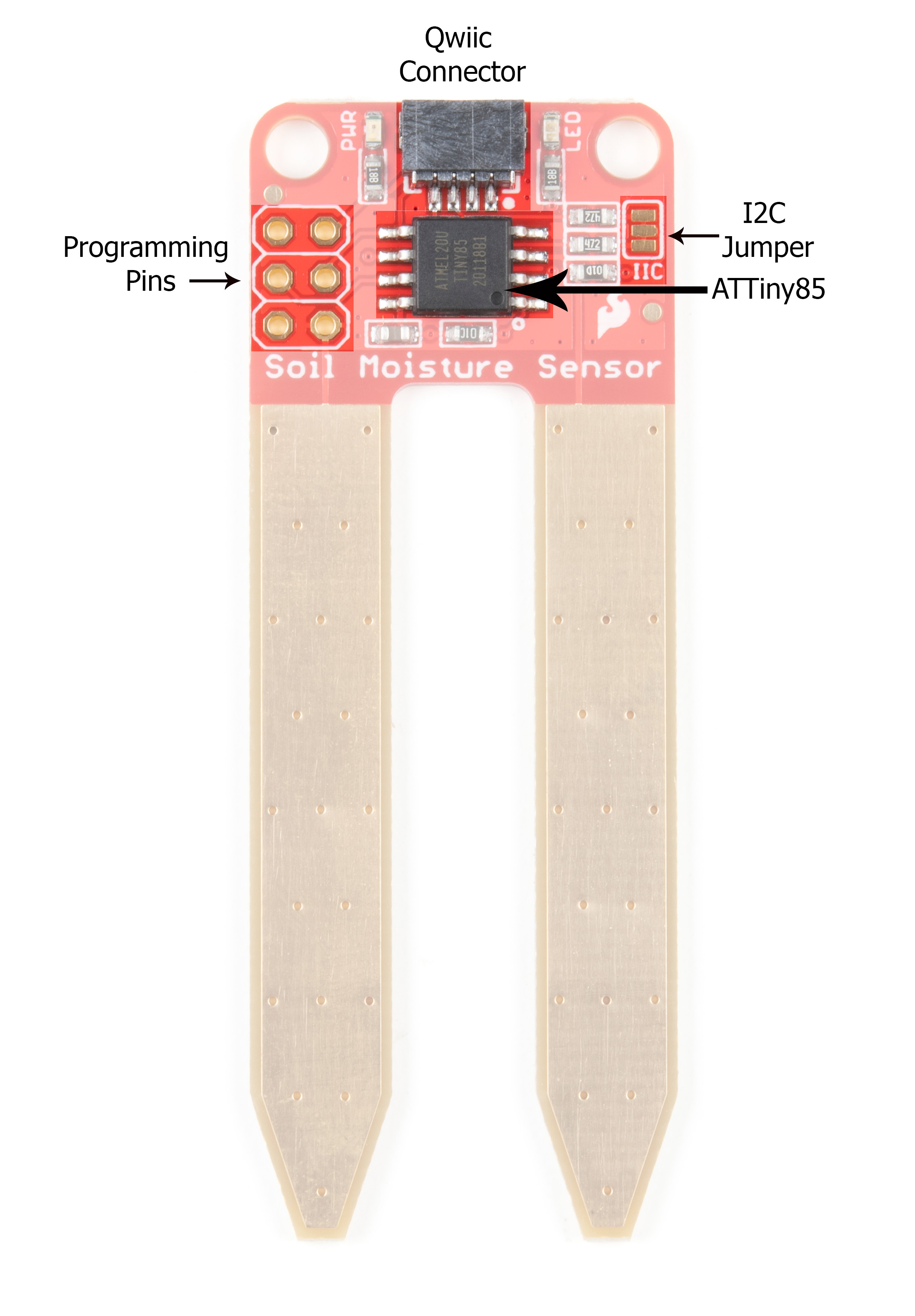
Programming Pins
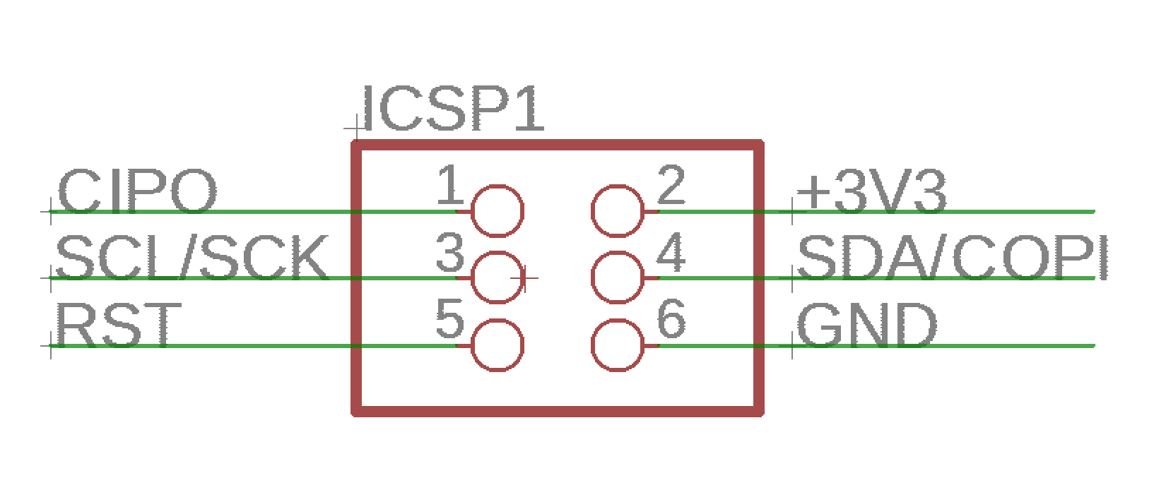
For those of you who are interested in the Qwiic system but aren't quite set up yet, there are pins broken out such that you can use I2C or SPI protocols. See the image below for pin functionality.
Theory of Operation
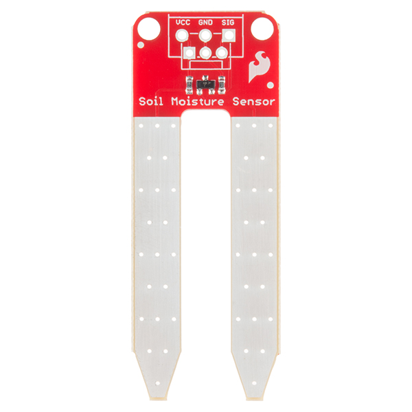
The two probes are acting as a variable resistor – more water in the soil means better conductivity and results in a lower resistance and a higher SIG out. Your analog readings will vary depending on what voltage you use for Vcc as well as the resolution of your ADC pins.
Powering the Soil Moisture Sensor
If you're using Qwiic to power your board, then you're good to go. Otherwise, we recommend powering the Soil Moisture Sensor with between 3.3V - 5V. Please note that the analog value returned will vary depending on what voltage is provided for the sensor.
One commonly known issue with soil moisture sensors is their short lifespan when exposed to a moist environment. To combat this, we've had the PCB coated in Gold Finishing (Electroless Nickel Immersion Gold).
Another way to extend the lifespan of your sensor is to only power it when you take a reading. Using a digital pin set to HIGH on an Arduino, for example, is an easy way to accomplish this. If you wish to power the sensor with more than a digital pin on your microcontroller can provide, you could always use a transistor.
Assembly
If you bought the Soil Moisture Sensor that already has the 3-pin screw terminal attached, you may skip this section. Likewise, if you are using the Qwiic connector!
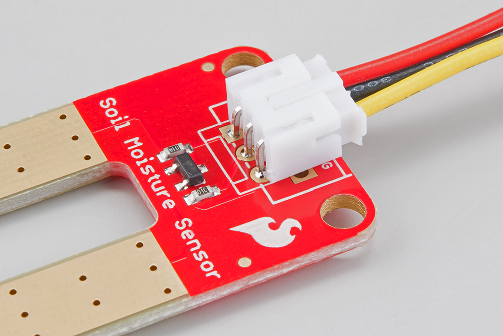
There are a few different options for connecting the sensor to your circuit. You can solder on a 3-pin JST Jumper Wire Assembly if you need to easily switch sensors on your project. This pairs nicely with our JST to Breadboard Jumper connector.
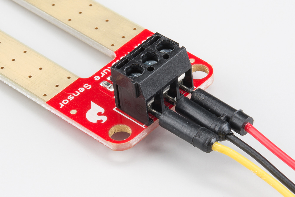
Another option is to solder on a 3-pin 3.5mm Screw Pin Terminal for a slightly more robust connection.
Of course, you can always solder some hookup wire straight to the sensor.
If you've opted for the Qwiic version of this board, assembly is a breeze.
Weatherproofing
If you intend to use this sensor outdoors, we recommend adding a little protection to the PCB to extend its lifespan. You could always use good ol' fashioned hot glue. However, hot glue does not hold up well in the sun and is only recommended for projects that will not be exposed to high temperatures. For projects that need to be able to withstand all the elements, you could use a conformal coating to cover the SMD parts on the PCB as well as your solder connections.