smôl ARTIC R2 Hookup Guide
 PaulZC
Hardware Overview
In this section we'll cover what's included on the smôl ARTIC R2 Peripheral Board.
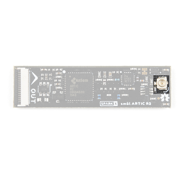
ARTIC R2
The heart of the smôl ARTIC R2 is, of course, the ARTIC R2 transceiver itself. This is a clever chip containing a Digital Signal Processor (DSP) which modulates transmit messages and demodulates received messages. The DSP can boot from on-board flash memory or from an external microcontroller via SPI. When transmitting, it produces a 1mW (0dBm) output signal which is fed to a separate power amplifier.
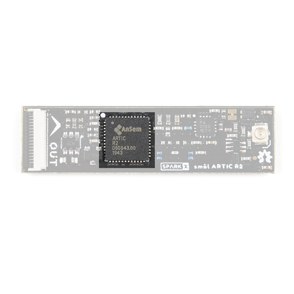
Our Arduino Library does all of the heavy lifting for you. By default, the library will tell the ARTIC R2 DSP to boot from the on-board flash memory. However, by changing one line of code, you can instead boot via SPI with your microcontroller providing the firmware for the DSP.
RF Amplifier
During transmit, the RFPA0133 power amplifier boosts the 0dBm (1mW) signal from the ARTIC R2.
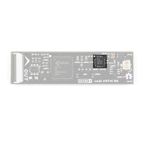
By default, the amplifier uses full gain and boosts the signal to approximately 25.8dBm (380mW). If you are using ARGOS 2 or 3 modulation and are transmitting from a 'noisy' environment, like a city, then you are probably going to need to use full power to ensure your messages get through. However, if you are using ARGOS 4 modulation and/or are transmitting from a 'quiet' environment, like the tundra or the ocean, then you will be able to transmit at reduced power.
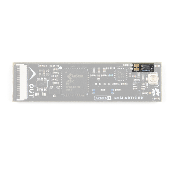
Gain Control
There are two ways to reduce the smôl ARTIC R2 transmit power. You can adjust the gain through software and the on-board opto-isolated gain control circuit.
Our Arduino Library can reduce the gain for you. If you call:
language:c
myARTIC.attenuateTXgain(true);
from inside your code, the opto-isolator will pull the RFPA0133's G8 pin low, reducing the gain by approximately 5dB. This also has the advantage of reducing the transmit current by approximately 80mA.
If you are experimenting with ARGOS 4 modulation, you may want to reduce the gain even further. You can do that by opening the split-pad jumper next to the opto-isolator. Opening the jumper will pull the RFPA0133's G16 pin low and will reduce the gain by approximately 11dB. If you haven't used jumpers before, please check out our tutorial.
How to Work with Jumper Pads and PCB Traces
Flash Memory
If you turn the smôl ARTIC R2 over, you will be able to see the small flash memory chip.
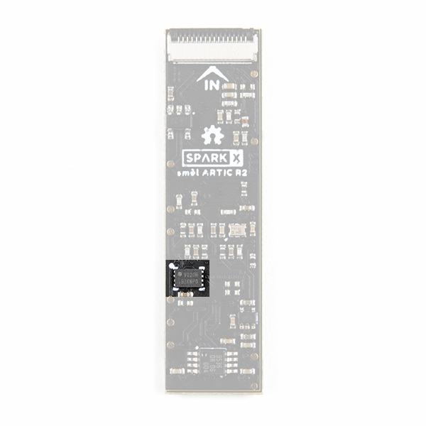
During production testing at SparkFun, we program the flash memory with the ARTIC R2 firmware (ARTIC006) and a Platform ID allocated by CLS. You will need to register the Platform ID on your ARGOS account to activate it.
GPIO Expander
The larger chip on the bottom of the board is a PCA9536 I2C GPIO expander.
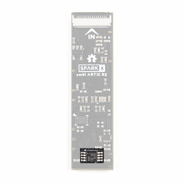
smôl only supports two GPIO signals, so we added a separate I2C GPIO expander to allow the ARTIC R2 RESETB, INT1 and BOOT signals, plus the RF amplifier G8 pin, to be controlled via I2C.
You won't need to communicate with the GPIO expander directly, our Arduino Library will do that for you, we're just letting you know why that chip is there.
Antenna
The antenna connection for the ARTIC R2 is u.FL.
Check out our tutorial if you haven't used u.FL before:
Three Quick Tips About Using U.FL
FPC Connections
Like all of our smôl boards, the ARTIC R2 Peripheral Board is equipped with two 16-way 0.5mm-pitch Flexible Printed Circuit connectors. FPCs are used to link the smôl boards together in a daisy-chain.
The pin-out for the smôl ARTIC R2 IN connector is as follows:
| IN Connector Pin No. | Signal Name | Function | Notes |
|---|---|---|---|
| 1 | PROC_PWR_EN | Processor Power Enable | Not used |
| 2 | 3V3 | 3.3V Power Rail | |
| 3 | GND | Power Ground / 0V | |
| 4 | SCLK | SPI Clock | Used to communicate with the ARTIC R2 |
| 5 | COPI | SPI Controller Out Peripheral In | Used to communicate with the ARTIC R2 |
| 6 | CIPO | SPI Controller In Peripheral Out | Used to communicate with the ARTIC R2 |
| 7 | CS0 | SPI Chip Select 0 | Used to communicate with the ARTIC R2 |
| 8 | CS1 | SPI Chip Select 1 | Connected to Pin 7 (CS0) on the OUT connector |
| 9 | CS2 | SPI Chip Select 2 | Connected to Pin 8 (CS1) on the OUT connector |
| 10 | GPIO0 | Power Control | Pull high to enable power for the ARTIC R2 |
| 11 | GPIO1 | General Purpose Input / Output 1 | Connected to Pin 10 (GPIO0) on the OUT connector |
| 12 | SDA | I2C Data | Used to communicate with the PCA9536 GPIO expander |
| 13 | SCL | I2C Clock | Used to communicate with the PCA9536 GPIO expander |
| 14 | GND | Power Ground / 0V | |
| 15 | 3V3 | 3.3V Power Rail | |
| 16 | V_USB | USB Power Rail (5V) | Not used |
The pin-out for the smôl ARTIC R2 OUT connector is as follows:
| OUT Connector Pin No. | Signal Name | Function | Notes |
|---|---|---|---|
| 1 | PROC_PWR_EN | Processor Power Enable | Not used |
| 2 | 3V3 | 3.3V Power Rail | |
| 3 | GND | Power Ground / 0V | |
| 4 | SCLK | SPI Clock | Used to communicate with the ARTIC R2 |
| 5 | COPI | SPI Controller Out Peripheral In | Used to communicate with the ARTIC R2 |
| 6 | CIPO | SPI Controller In Peripheral Out | Used to communicate with the ARTIC R2 |
| 7 | CS0 | SPI Chip Select 0 | Connected to Pin 8 (CS1) on the IN connector |
| 8 | CS1 | SPI Chip Select 1 | Connected to Pin 9 (CS2) on the IN connector |
| 9 | CS2 | SPI Chip Select 2 | Not connected |
| 10 | GPIO0 | General Purpose Input / Output 0 | Connected to Pin 11 (GPIO1) on the IN connector |
| 11 | GPIO1 | Not connected | |
| 12 | SDA | I2C Data | Used to communicate with the PCA9536 GPIO expander |
| 13 | SCL | I2C Clock | Used to communicate with the PCA9536 GPIO expander |
| 14 | GND | Power Ground / 0V | |
| 15 | 3V3 | 3.3V Power Rail | |
| 16 | V_USB | USB Power Rail (5V) | Not used |
We use a technique called waterfalling on the CS and GPIO signals. If you haven't used waterfalling before, please check out the smôl Hookup Guide.