Setting Up the Pi Zero Wireless Pan-Tilt Camera
 SFUptownMaker
Hardware Assembly
To assemble the hardware, we need to:
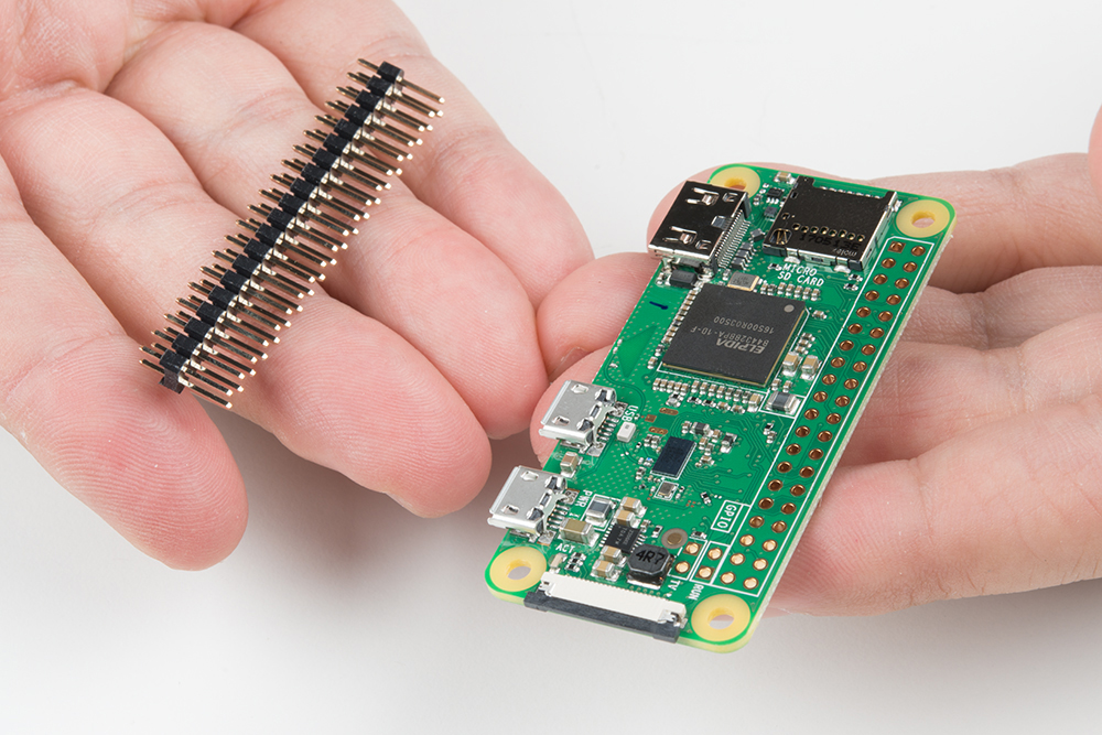
- Solder headers to the Raspberry Pi Zero W.
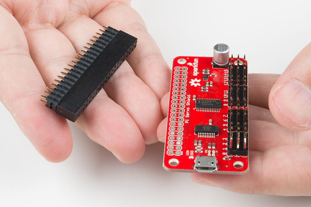
- Solder headers to the Pi Servo Hat.
- Install the Pi Servo Hat on the Pi Zero W.
- Assemble the pan-tilt hardware and connect the servos to the hat.
Let's walk through these steps in more detail!
Solder Headers to the Raspberry Pi Zero W and the Pi Servo Hat
We recommend soldering the male header to the Pi Zero W and the female to the Pi Servo Hat. If you have any issues with soldering, please check out our learn to solder tutorial.
Assemble the Pan-Tilt Mechanism
Assembly of the pan-tilt mechanism is fairly straightforward. The trickiest part is making sure the servo motors are centered during assembly.
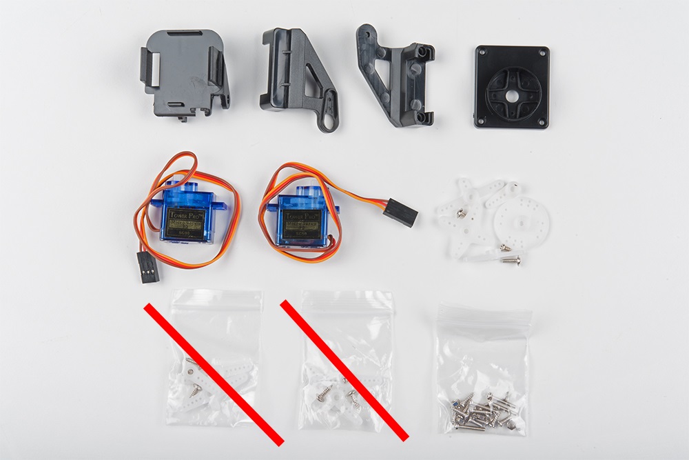
Here's the family portrait of the stuff that comes in the kit. You won't be needing the servo horns that come packaged with the servo motors, just the ones that come packaged separately.
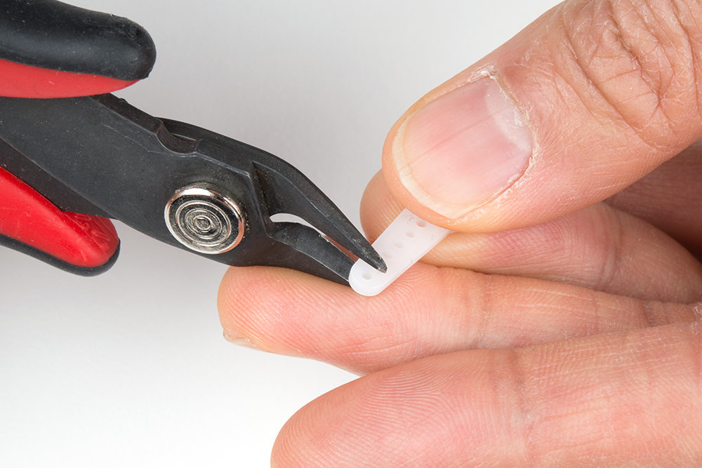
Start by identifying the servo horn with two long arms and two short arms. You'll need to clip off the long arms, as shown below.
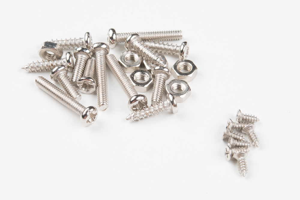
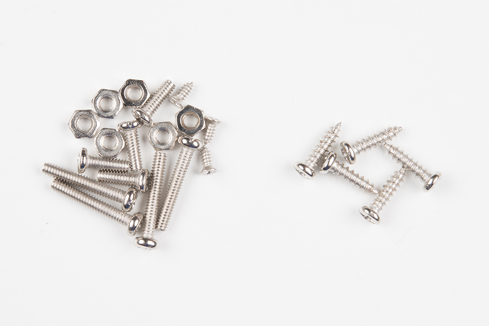
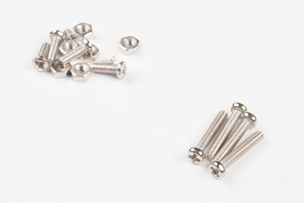
Identify the smallest screws in the baggie of screws that came with the kit. These will be used to affix this horn to the base of the pan-tilt mechanism.
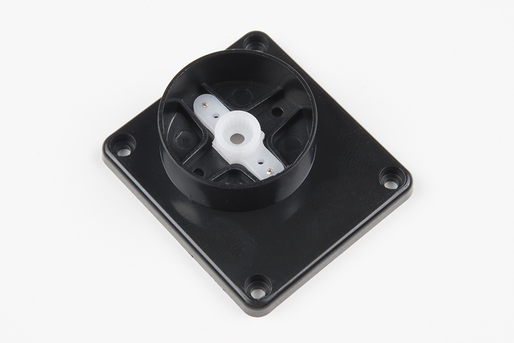
Place the horn in the base as shown, then screw it down by inserting the screws from the bottom and threading them into the horn. Note that there will be extra screws, even beyond the ones to be used later. This is generally true of all the screws in this set.
Next, identify the larger self-tapping screws. These will be used for assembling the next part of the mechanism.
Find the two pieces pictured below that will sandwich the first servo. Note the orientation of the servo in these pieces.

Here's the sandwiched servo. Again, note the orientation for proper assembly.

Here, you can see where the screws identified a couple of steps ago fit into our servo sandwich. Tighten them down, but not too much.
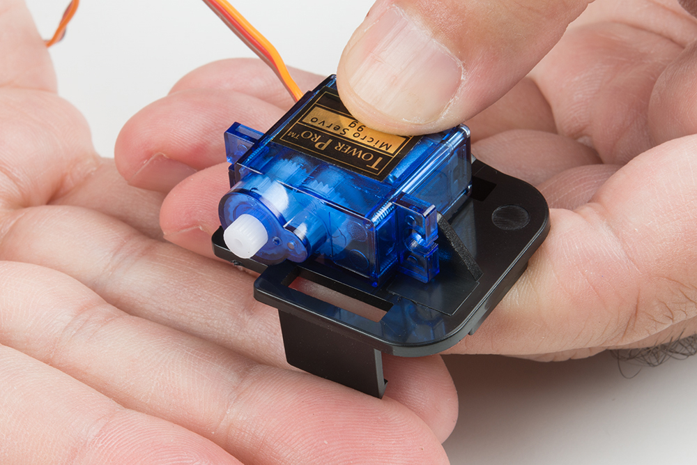
Now fit the shaft of the servo into the fitting on the horn that you previously installed into the base. This is the point where you need to make sure that the shaft is roughly centered in order for the entire assembly to work properly. I do this by turning the shaft all the way to one extreme, then turning it 90 degrees back in the other direction. Then, I remove the base and line it up with the body of the servo motor.
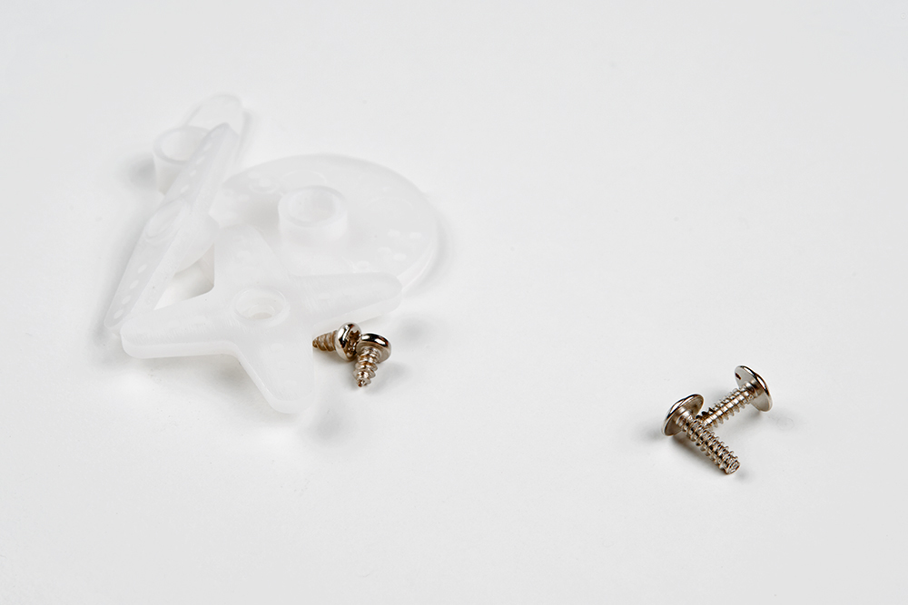
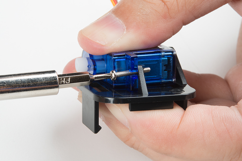
Find the two longer screws that came with the horn kit in the set to attach the base to the servo. There will likely be only two of these, and you need both, so don't lose one! Insert the screw to the bottom and tighten the screw to attach the two parts together.
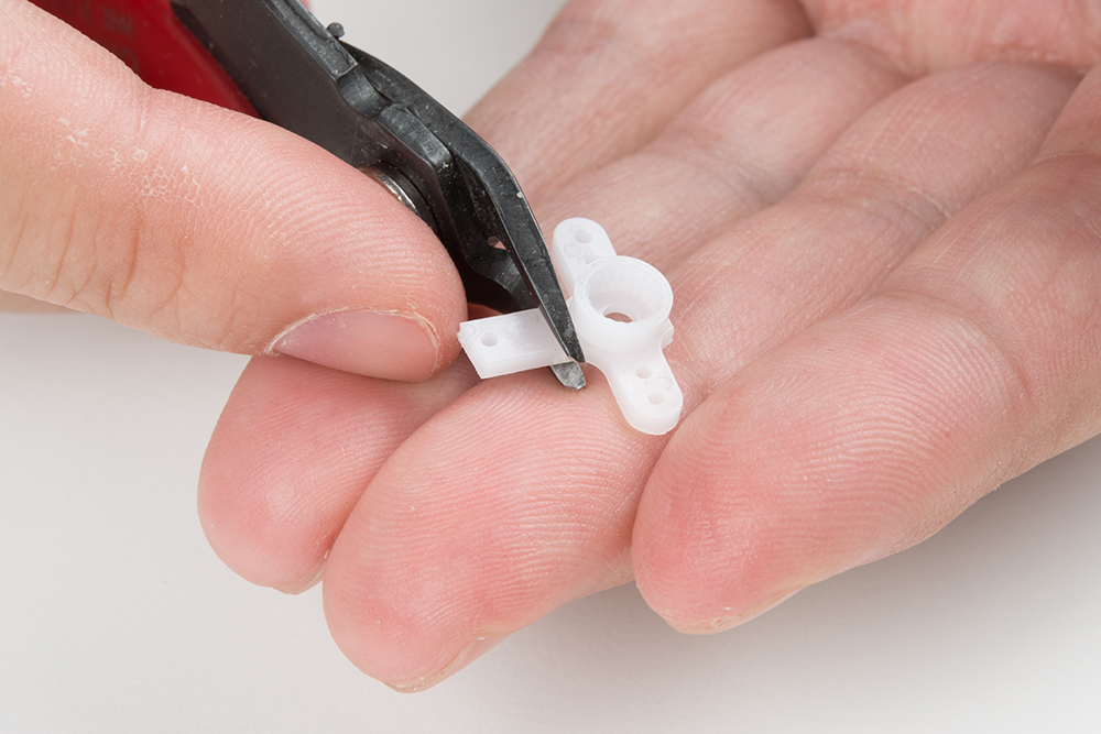
You'll now need the single arm servo horn with 5 holes, as shown in the image below on the left. If the single arm servo with 5 holes was not included in the kit, you will need to modify one of the servo horn with 6 holes that was packaged separately. Shorten the horn by clipping off one hole as shown in the image below on the right and checking to see if it fits the mold on the tilt bracket. Be careful when clipping and make sure that you do not clip off too much of the horn.
 |
 |
| Single arm servo horn with 5 holes. | Single arm servo horn with 6 holes being clipped. |
Install the single arm servo horn as shown below. You'll need two of the small self-tapping screws from the first step to affix it to the mechanism.
 |
 |
| Attaching the single arm servo horn. | Attaching the clipped single arm servo horn. |
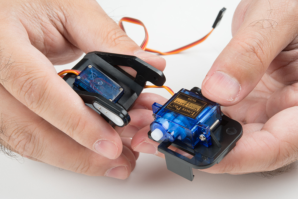
You'll now need the second servo motor and the last piece of the mechanism. The image below shows the relative orientation of these two pieces.

Here's a picture of the two pieces assembled to one another.
Now, find the longest machine screws in the baggie, as shown below. Once again, you'll find that there are more of these than you need.
Thread these screws through the stand off wings on the servo motor and into the last piece of the mechanism. You can use nuts for these if you like, but I've found it to be unnecessary as they thread into the mechanism quite snugly without the nut.
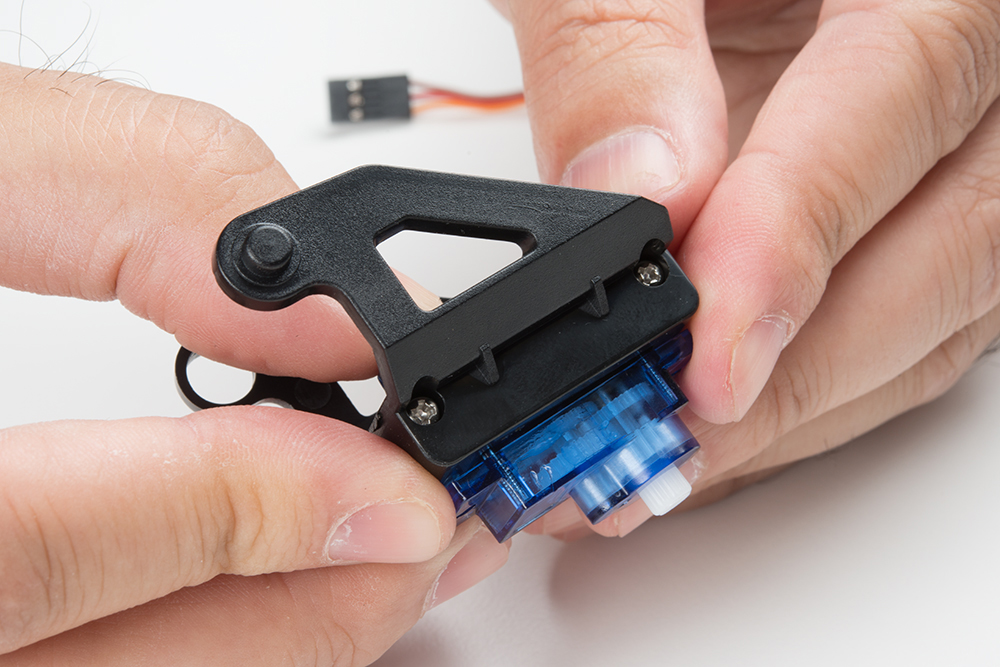
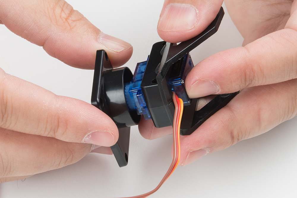
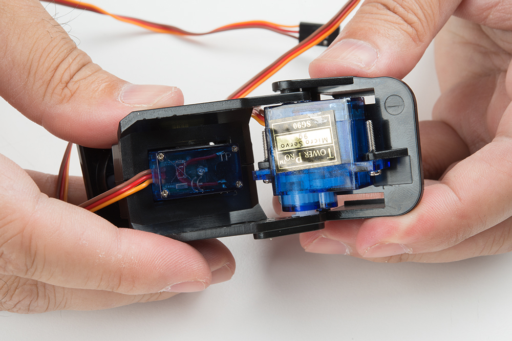
Now connect the two major pieces of the assembly together. The image below shows the orientation of these two parts.
You may need to assemble and disassemble these two parts a couple of times to find the right rotational position of the servo motor so that the tilting portion has its full range of motion. Here's an image of the two bits put together.
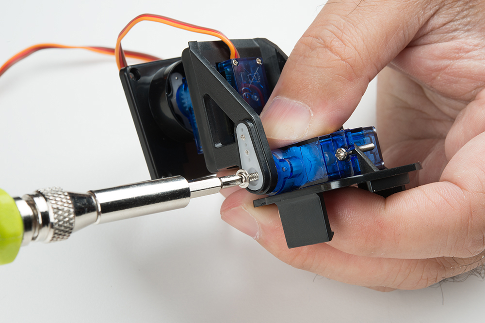
Take the final screw that you identified above as a horn attaching screw and use it to secure the horn to the servo motor.
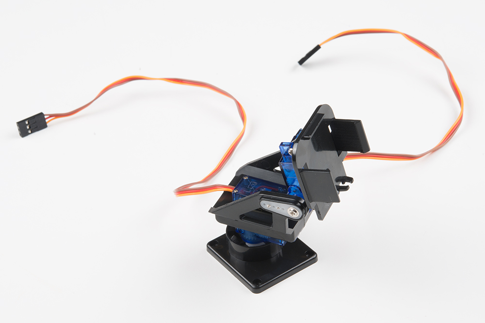
Congratulations, you've finished assembly of the pan-tilt mechanism!
Solder the Headers onto the Pi Zero W and Pi Servo Hat
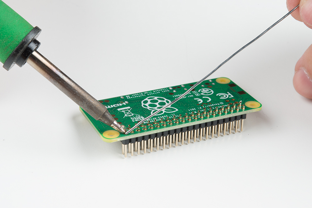
We suggest soldering the male headers onto the Pi Zero W.
My favorite trick for this type of situation is to solder down one pin, then melt the solder on that pin with the iron held in my right hand and use my left hand to adjust the header until it sits flat as shown below. Make sure that you are soldering with the header's shorter side and the longer pins are on the component side. After tacking down one pin, finish soldering all the pins down to the Pi Zero W.
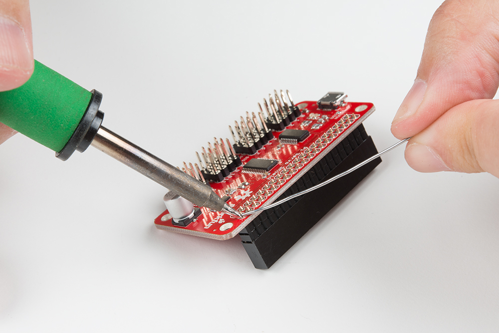
Repeat the steps with the female header and the Pi Servo Hat.
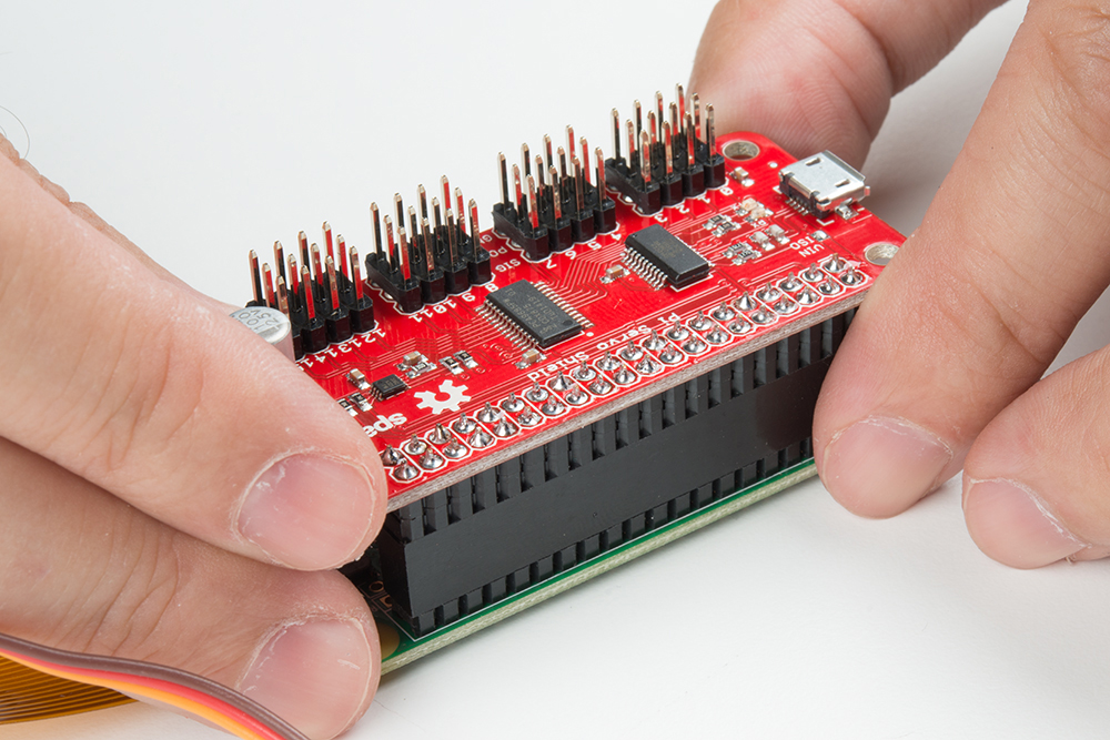
Make sure to insert the short pins from the bottom of the board and add solder to the component side so that the Pi Servo Hat stacks on top of the Pi Zero W's male header pins. You will also need to make sure that the header is sitting level before soldering down all the pins.
Affix the Camera Module to the Pan-Tilt Mechanism
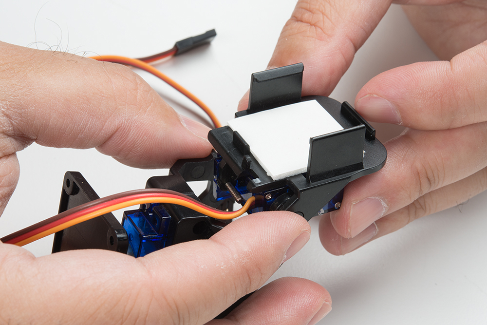
Start by affixing the double stick foam tape to the pan-tilt mechanism as shown in the image below.
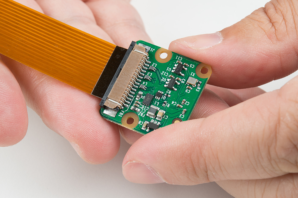
Next, attach the flex cable to the camera module. Take note of the copper "fingers" on the end of the cable. The side with the fingers on it should be facing the camera module circuit board. See the image below.
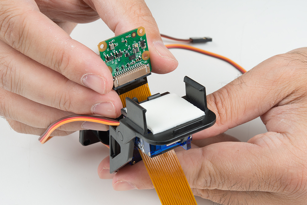
Thread the flex cable through the pan-tilt mechanism as shown below, then press the back of the camera board against the double stick tape to adhere it to the pan-tilt mechanism.
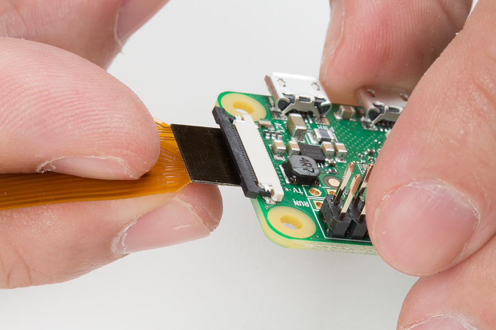
Insert the flex cable from the camera into the Pi Zero W. As was the case with the other end, the side of the cable with the copper fingers should be facing the circuit board. Don't forget to close the clamping mechanism!
You may now attach the Pi Servo Hat to the header on the Pi Zero W.
Connect the Servo Motors to the Pi Servo Hat
The servo motors need to be connected to channels 0 and 1 on the Pi Servo Hat. Connect the "pan" servo (the one on the bottom) to channel 0 and the "tilt" servo to channel 1.
| Pi Servo Hat (CH 0) |
Pan Servo (Bottom of Pan-Tilt Mechanism) |
Pi Servo Hat (CH 1) |
Tilt Servo |
|---|---|---|---|
| SIG | Control Signal (Orange) | SIG | Control Signal (Orange) |
| POW | Vcc (Red) | POW | Vcc (Red) |
| GND | GND (Brown) | GND | GND (Brown) |
Once connected, your setup should look like the image below.
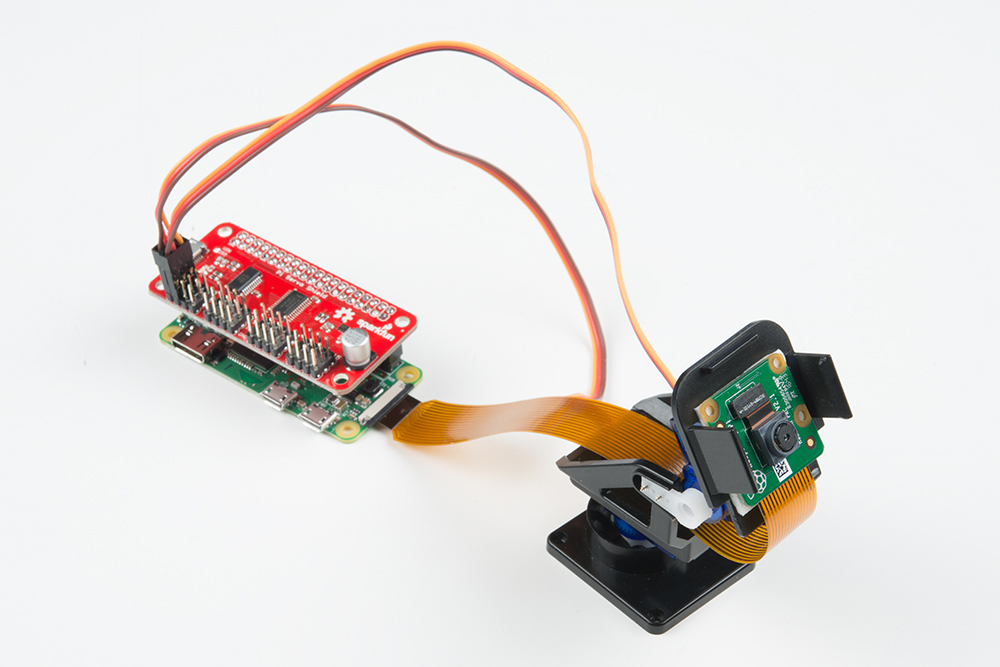
This completes the necessary steps of the hardware assembly!