Servo Trigger Hookup Guide
 Byron J.
Getting Started Quickly
Let's jump in and build a circuit to show how the Servo Trigger works!
Materials and Tools
You'll need to following materials to build this example circuit.
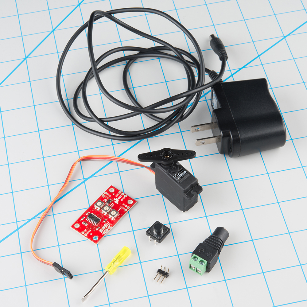
- The Servo Trigger module.
- A hobby servo motor - we'll be using our micro size metal gear servo.
- A switch - any momentary-contact switch is suitable, so we'll use a 12mm tactile pushbutton.
- A 5V power supply.
- A barrel jack adapter to make conecting the power supply easier.
- A 3-pin section of a snappable header, either straight or right-angle.
- A small screwdriver to adjust the trimpots.
- Finally, not shown, we'll need some hookup wire and soldering tools.
Hardware Hookup
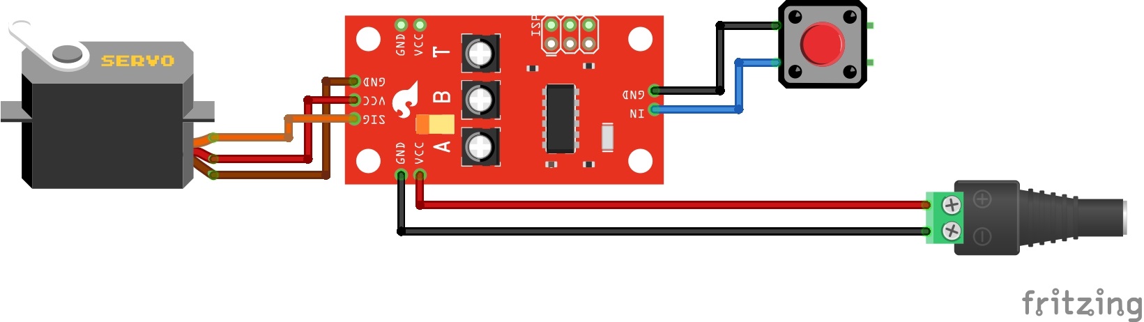
You will need to make the following connection. Below is a Fritzing diagram of the parts connected to the Servo Trigger. We'll go through step by step in the next section showing how to connect the components together.
Beginning Steps
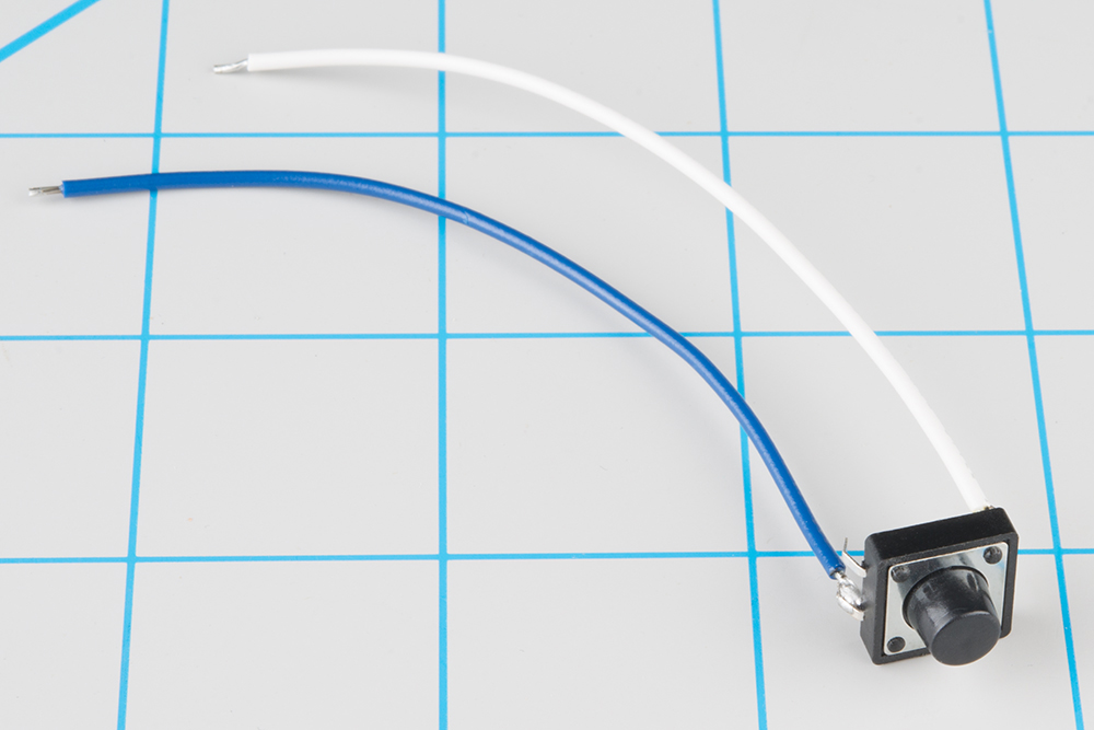
To start, solder some wires to the tactile switch. If you solder to legs on on opposite corners (top-right and lower-left, for instance), you can be confident that you'll get a contact closure when you press the button.
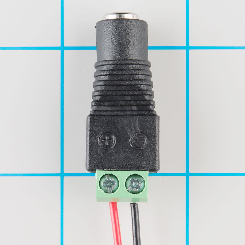
Then prepare the power plug pigtail. Take a pair of wires, and strip the ends, then screw them to the power jack adapter -- if you look closely at the adaptor, you'll notice that there are a small + and - embossed in the plastic. We used a red wire for VCC on the + terminal, and a black wire for ground on the - terminal.
Next, solder the 3-pin header to the 3 pads on the end the board, and plug the servo into the the header. Be careful to get the plug oriented correctly -- you can check the color code table in the previous section, or consult the servo manufacturer's datasheet.
Then solder the switch wires to the IN and GND pads on the Servo Trigger, and the power pigtail to the VCC and GND pads on the edge of the board. These are mirrored on opposite edges of the board -- they're wired in parallel, so you can use either set of pads. The red wire should connect to the VCC pad, and the black to GND.
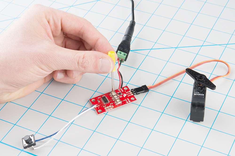
Before we power up, take a moment to double-check your work against the photo below (click on the picture for a larger version). In particular, make sure that the power and servo connections are oriented correctly.
Adjust the trimpots on the back of the board. Set A fully counterclockwise, B fully clockwise, and set T to the middle.
Finally, apply power. The servo will probably jump to a new position as you do this.
Then, press and hold the switch. The servo will rotate, taking a couple of seconds to reach its new position. Release the switch, and it will go back to the starting point.
Now you can adjust the trimpots to configure the servo.
Asets the position the servo sits in while the switch is open.Bsets the position the servo moves to when the switch is closedTsets the time it takes to get from A to B and back.
Turning the position pots clockwise will make the motor turn further clockwise. If A is higher than B, then the servo will turn counterclockwise when the switch is actuated. The timing range is adjustable between 50 milliseconds and 3 seconds. The transit time is constant -- when set to 2 seconds, the servo will take 2 seconds to move between A and B, regardless of how close the position settings are.
In the next section, we'll explore some of the finer details of the Servo Trigger.