Servo Trigger Hookup Guide
 Byron J.
Servo Motor Background
In the most generic sense, a "servomechanism" (servo for short) is a device that uses feedback to achieve the desired result. Feedback control is used in many different disciplines, controlling parameters such as speed, position, and temperature.
In the context we are discussing here, we are talking about hobby or radio-control servo motors. These are small motors primarily used for steering radio-controlled vehicles. Because the position is easily controllable, they are also useful for robotics and animatronics. However, they shouldn't be confused with other types of servo motors, such as the large ones used in industrial machinery.
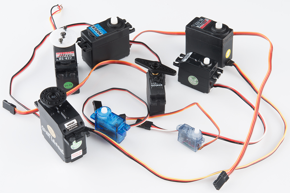
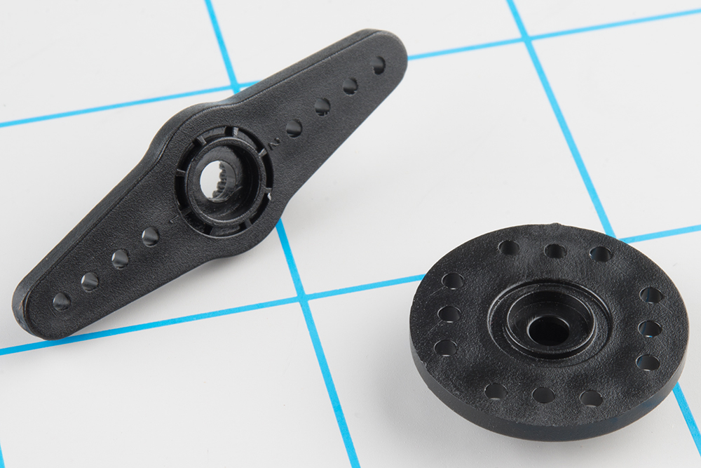
RC servos are reasonably standardized - they are all a similar shape, with mounting flanges at each end, available in graduated sizes. Servos often come with several wheels or levers, known as "horns", than can be attached to the shaft, to fit the device they are operating.
Electrical Connection
Most hobby servos use a standard type of 3-pin plug, with the same control signaling, which makes RC servos reasonably interchangeable.
The connector is a 3-pin, 0.1" pitch header. One thing that can be confusing is that the wiring color code isn't always consistent -- there are several color codes at play. The good news is that the pins are usually in the same order, just that the colors on them are different.
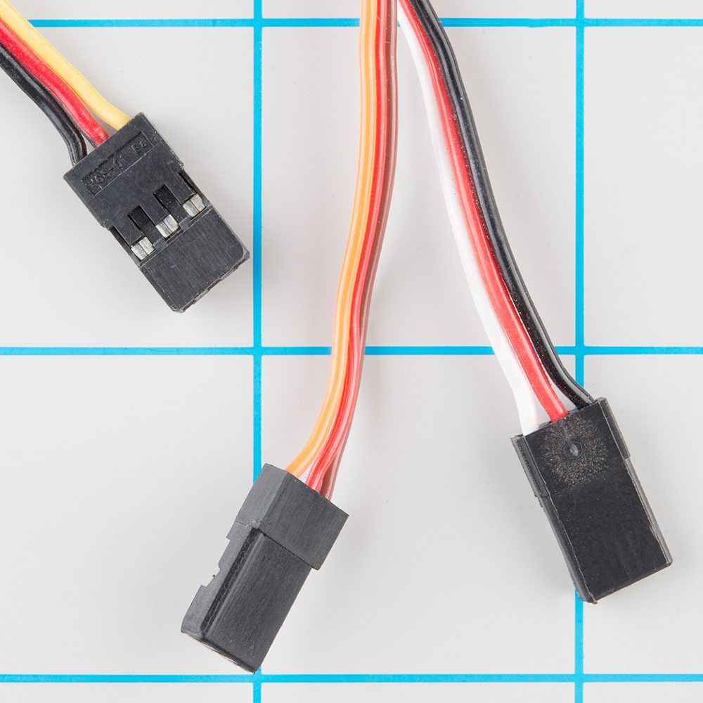
The table below summarizes common color schemes.
| Pin Number | Signal Name | Color Scheme 1 (Hitec) |
Color Scheme 2 (JR) |
Color Scheme 3 (Futaba) |
|
| 1 | Ground | Black | Brown | Black | |
| 2 | Power Supply | Red | Brown | Red | Red |
| 3 | Control Signal | Yellow | White | Orange | White |
Powering Servos
In RC vehicles, 5.5V is the nominal battery voltage. It will be somewhat higher after a charge, and it will droop as the batteries discharge. As the voltage drops, the available torque also drops -- if you've driven RC vehicles, you're no doubt familiar with the loss of control that occurs as the batteries get weaker. It starts to feel sluggish just before it dies.
If you're not using batteries, the 5VDC available from a garden variety power supply is a good option. If you're using the Servo Trigger to control your motor, the absolute maximum supply voltage that should be applied is 5.5 VDC.
Regardless of how you're powering them, it's worth noting that the current consumed by the motor increases as the mechanical loading increases. A small servo with nothing attached to the shaft might draw 10 mA, while a large one turning a heavy lever might draw an Ampere or more!
Control signal
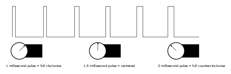
Servos are controlled with a specific type of pulse train signal. The pulses occur at a 20 mSec (50 Hz) interval, and vary between 1 and 2 mSec in width. The Pulse Width Modulation hardware available on a microcontroller is a great way to generate servo control signals.
Common servos rotate over a range of 90° as the pulses vary between 1 and 2 mSec -- they should be at the center of their mechanical range when the pulse is 1.5 mSec.
Internally, the mechanism of a servo motor uses a potentiometer attached to the rotating shaft to sense the position. It measures the width of the incoming pulse, and applies current to the motor to turn the shaft correspondingly.
Here are the insides of a servo that's been dissected. You can see the DC motor, position potentiometer, and a small PCB. The PCB has a chip on one side, possibly a small microcontroller.
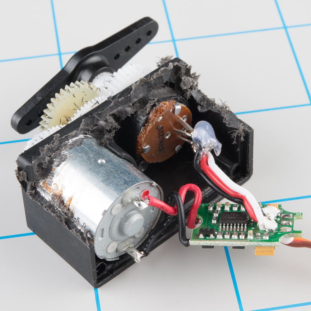
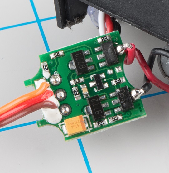
The other side of the PCB has some discrete transistors, probably in an H-bridge configuration, which allow the controller to steer current through the motor in either direction, for both clockwise and counterclockwise rotation.
One Other Useful Servo
Ordinary RC servos turn over a 90° range -- it's useful for turning a steering linkage, or adjusting the control surfaces on an airplane, but not so useful as a drive mechanism. That's where full or continuous rotation servos come in.
Rather than controlling position, the continuous rotation servo translates the same pulse-train signal into the rotational speed and direction of the shaft. Otherwise, they're very similar to regular RC servos -- they use the same power supply, control signals, 3-pin connector, and are available in the same sizes as RC servos.
The overall speed is relatively low -- around 60 RPM is a common maximum rate -- if you need higher rotation speed, servos aren't the best fit -- DC gearmotors or brushless DC motors are more likely candidates, but they aren't directly compatible with servo control signals.
With the Servo Trigger
The Servo Trigger is capable of controlling both regular and continuous rotation servos. We'll explore some more specific use cases in the following sections.