Servo Trigger Hookup Guide
 Byron J.
More Details
On The Board
Let's look at the components on the board and examine how it works.
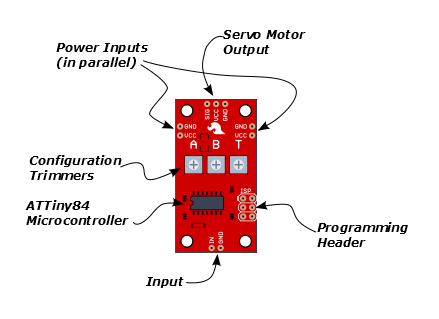
The heart of the Servo Trigger is an Atmel ATTiny84 microcontroller, running a small program that implements the servo control features we are discussing here. Just because the Servo Trigger saves you from needing to write code doesn't mean that there's no programming involved!
The servo control signal is generated using a 16-bit hardware timer. It runs off a 1 MHz clock, counting to 20000 to generate the 20 mSec (50 Hz) period and configured to generate pulses that range from 1000 to 2000 µSec (1 to 2 milliseconds).
The three potentiometers are connected as voltage dividers between VCC and ground. They are read using analog inputs ADC0, ADC3, and ADC7.
The switch input is read using PortA, input pin 1. It is debounced in software and can be configured to watch for a switch closure, or a logic level pulse.
If you're interested, you can download the schematic, PCB layout and firmware files from the Servo Trigger GitHub Repository. The board also includes the common 6-pin in-system-programming header, which we'll discuss in the Expert Exercises section. But we're getting a bit ahead of ourselves -- there are configuration options you can use without programming.
Configuration
The Servo Trigger has a couple of configuration options. If you look at the back of the PCB, you'll notice two solder jumpers that can be used to change Servo Trigger's response.
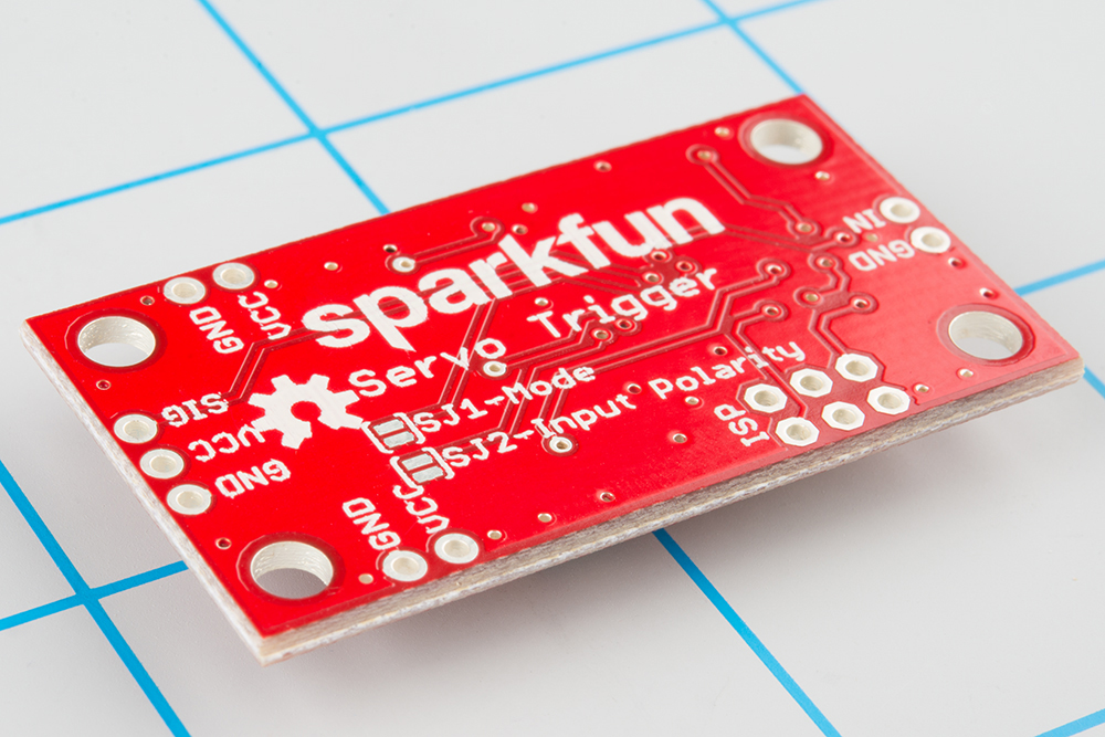
When it first powers up, the servo trigger reads these jumpers, and configures itself accordingly.
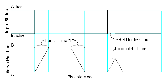
Modes
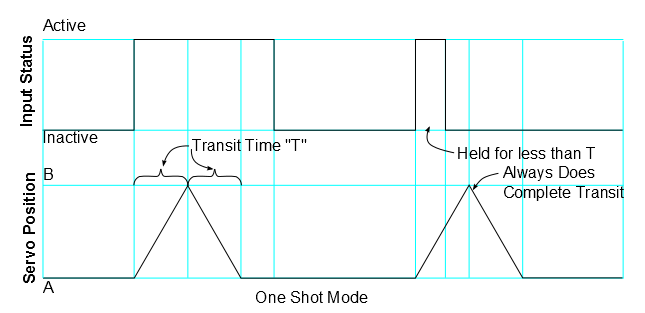
The Servo Trigger has two different servo control modes, selected with solder jumper 1 (SJ1). They can be used to tailor the response of the board for different applications.
The default mode implements bistable control -- the servo will sit at position A or position B, depending on the input actuation. While the switch stays in a state, the servo stays in the corresponding position -- it is stable in two different states.
This behavior can be changed by flowing solder between the pads of the jumper.
With the solder jumper closed, the mode changes to one-shot or monostable. When the input is actuated, the servo will move from A to B, then back to A -- the servo is stable in the A position, and only passes through the B position momentarily. Regardless of when the input is cleared, the servo will make a complete transit.
Input Polarity
The Servo Trigger input sensitivity can also be changed, using solder jumper 2 (SJ2).
The default configuration, with no solder applied, configures the Servo Trigger for use with a normally-open switch, with the internal pull-up resistor on the microcontroller enabled. This configuration is also suitable for use with an active-low logic input.
With SJ2 closed, the internal pull-up is disabled, and the input is set as an active-high logic input.
If SJ2 is closed, be careful about powering up the Servo Trigger when the input is not connected to anything. When the input is floating, it can randomly toggle between active and inactive and may cause the motor to behave unpredictably.
A note about nomenclature here: since the input polarity can be swapped, it can be hard to talk about -- the voltage might be high, but when the sense is inverted, it indicates that the input isn't being actuated. To help navigate this, the polarity-neutral terms active or asserted are used to describe when the input is being used, and inactive or deasserted to describe the default state.
More components
The servo trigger can be used with a wider variety of external components than used in the example above. We used a mid-sized servo, though we have many other candidates, in a wide variety of sizes & torque ratings.
You can also use different switches, such as micro switches and foot pedal switches.
Power Notes
Compared to a servo motor, the Servo Trigger board draws very little current -- roughly 5 mA.
The motors draw significantly more -- a quick bench test using a small servo, with only a lightwieght horn attached, shows the motor draws 10 mA sitting idle, and about 70 mA while moving. Grabbing the horn and twisting causes the controller to apply current to the motor, counteracting the twist. It drew 700 mA during this test -- a larger servo could draw even more!
These currents can get surprisingly high as you add more motors to the system -- you'll need to select a power supply with adequate capacity.
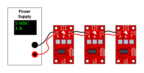
The Servo Trigger is designed to make it easy to daisy chain boards -- you can simply connect the VCC and GND pads on adjacent boards.
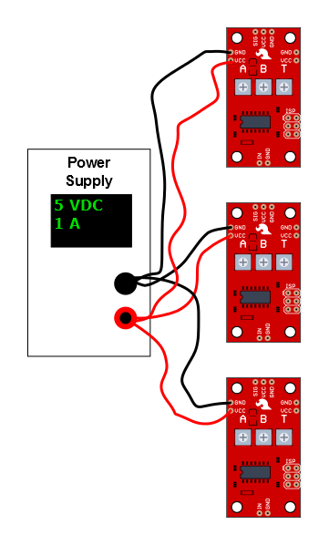
In applications where the motors are moving non-trivial loads, it's a better bet to use heavier gauge wires and give each Servo Trigger a direct connection to the power supply. The configuration is commonly known as "star power."
When in doubt, grab a multimeter, measure the current consumed, and check whether VCC at the board input is falling below the rated voltage when the servos are turning.
Troubleshooting
If there's no motion when you actuate the input, first check that A and B are not set the same, otherwise there's no position change!
If you're feeding the input with a logic signal from an external device, be sure to drive the signal for more than 50 milliseconds. The PWM signal is updated every 50 mSec, and events shorter than that may missed.
It's also possible to set T shorter than the time it take the servo motor to physically rotate. In this case, the motor may not reach B before returning to A. Try turning up T, to see if a longer transition time allows the motor to turn.