Sending Sensor Data Over WiFi
 ROB-24601
Introduction
We’re all familiar with WiFi. It runs our home, let’s us stream our favorite movies, and keeps us from having to talk with other people when we’re at a coffee shop. But there's more ways to use WiFi than simply accessing the internet through different applications. In this tutorial, we'll show you how to set up your own peer-to-peer network to sense data from one area and send that data to an LCD screen somewhere else without needing any internet connection or routers. This a great first step in being able to remove the wires from any embedded physical computing application.
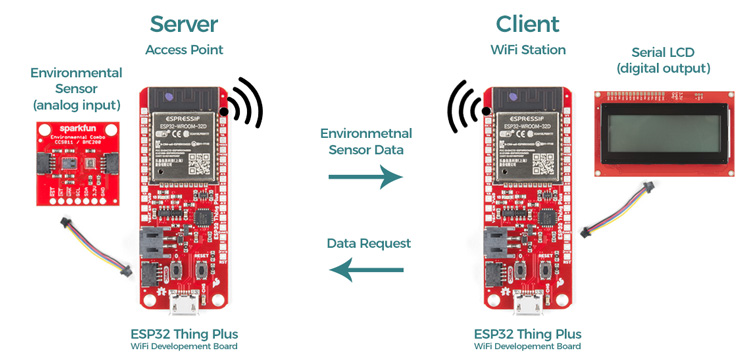
The Project: Wirelessly Monitor Temperature, Humidity, and Barometric Pressure
For this build, we're going to create a simple point-to-point closed WiFi system that reads the data from an environmental sensor and sends it to a display somewhere else. We'll keep this example as simple as possible by using our hardware, utilizing the Qwiic Connect System to connect our hardware without the need for soldering. The hardware includes a pair of ESP32 Thing Plus Wroom modules, a Qwiic Environmental Combo Breakout, a SparkFun Qwiic Single Relay, and a couple of Qwiic Cables. (And of course, a power supply - either battery or wall charger - for each.) You can add all the items of this tutorial to your cart using the wishlist below.
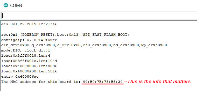
Step 1: Obtaining MAC Addresses
In order to communicate with any device over WiFi, we need to know its Media Access Control Address, or MAC address. There’s a short and simple Arduino sketch that will find the MAC address of each device, and this one should go in your drawer of super-useful Arduino utility sketches right next to your I2C sniffer.
/*
 * MAC Address Finder
 * Run this on each of your WiFi-enabled
 * boards to get their MAC addresses, so
 * you can plug them into your code,
 * allowing your components to connect
 * on power-up or after power-cycling
 * without the need for any intervention!
 *
 * Once you've uploaded the code, open
 * the Serial Monitor, hit the reset
 * button on your board, and write down
 * the MAC address.
 * (I use a label maker to put the MAC
 * address on the back of each board.)
 */

#include "WiFi.h"

void setup(){
  Serial.begin(115200);

}

void loop(){
  WiFi.mode(WIFI_STA);
  Serial.print("The MAC address for this board is: ");
  Serial.println(WiFi.macAddress());
  while(1){     // This holds the loop, so it doesn't
    }           // print the info a million times.
}
When I was first starting to work with WiFi boards, I would find the MAC address, write it on a sticky note, then put that on each board. Of course I would then throw them all in my bag, go from my home workspace into SparkFun HQ and pull all the boards out, only to find that the sticky notes were all stuck to each other in the bottom of my bag. Useless! Since then I’ve been using a label maker to tag the back of each board. I would recommend against using a permanent marker on your boards for this since the MAC addresses can be changed.
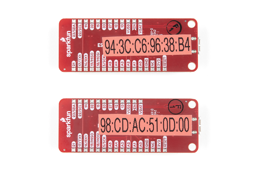 A label maker is a non-permanent solution to putting the MAC address on each board.
Step 2: Connecting the Hardware
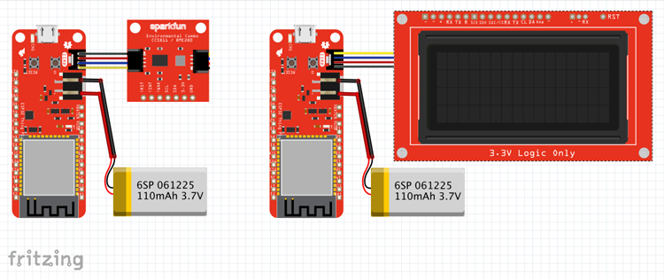
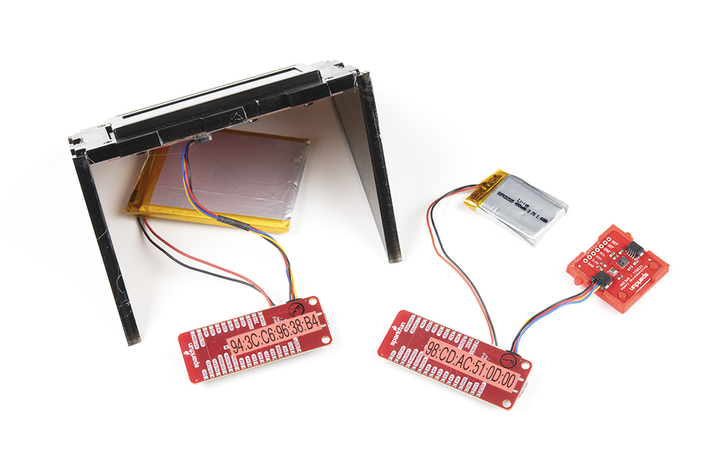
As stated before, working with SparkFun's Qwiic Connect System is very simple and this project will only require you to make 6 total connections. To one of the ESP32 Thing Plus boards (the transmitter or server board), we’ve connected the SparkFun Qwiic Environmental Breakout, and to the other ESP32 Thing Plus board (the receiver or client board), the Qwiic 20x4 SerLCD RGB Backlight Display. Note that since we’re only using the BME280 sensor from the environmental combo board, you could also use our Atmospheric Sensor Breakout - BME280 without any change to the code, if you would like to use that sensor board instead.
Step 3: Uploading the Code
For this example we have two Arduino sketches - one for the data transmitter, and one for the data receiver.
Copy this sketch and upload it to your transmitting board, the one with the Qwiic Environmental Combo connected to it. Make sure that before you upload it, you insert the MAC address of your receiving board on line 34 of the sketch, so that, in our case,
uint8_t broadcastAddress[] = {0xFF, 0xFF, 0xFF, 0xFF, 0xFF, 0xFF};
would become
uint8_t broadcastAddress[] = {0x94, 0x3C, 0xC6, 0x96, 0x38, 0xB4};
Full Transmitter Code
The proper board (SparkFun ESP32 Thing Plus) should still be selected, just make sure you've connected to the proper COM port, and upload the following sketch.
/* WiFi Peer-to-Peer example, Transmitter Sketch
 * Rob Reynolds, SparkFun Electronics, November 2021
 * This example uses a pair of SparkFun ESP32 Thing Plus Wroom modules
 * (https://www.sparkfun.com/products/15663, a SparkFun Qwiic Environmental
 * Combo Breakout (https://www.sparkfun.com/products/14348), and a SparkFun
 * Qwiic 20x4 SerLCD - RGB Backlight (https://www.sparkfun.com/products/16398).
 *
 * Feel like supporting our work? Buy a board from SparkFun!
 * https://www.sparkfun.com/
 *
 * License: MIT. See license file for more information but you can
 * basically do whatever you want with this code.
 *
 * Based on original code by
 * Rui Santos
 * Complete project details at https://RandomNerdTutorials.com/esp-now-esp32-arduino-ide/
 *
 * Permission is hereby granted, free of charge, to any person obtaining a copy
 * of this software and associated documentation files.
 *
 * The above copyright notice and this permission notice shall be included in all
 * copies or substantial portions of the Software.
*/

#include <esp_now.h>
#include <WiFi.h>

#include <Wire.h>            // Used to establish serial communication on the I2C bus
#include "SparkFunBME280.h"  // Install library for the BME280
BME280 mySensor;             // Define sensor


// REPLACE WITH YOUR RECEIVER MAC Address
uint8_t broadcastAddress[] = {0xFF, 0xFF, 0xFF, 0xFF, 0xFF, 0xFF};

// Structure example to send data
// Must match the receiver structure
typedef struct struct_message {
  float a;
  float b;
  float c;
} struct_message;

// Create a struct_message called myData
struct_message myData;

// callback when data is sent
void OnDataSent(const uint8_t *mac_addr, esp_now_send_status_t status) {
  Serial.print("\r\nLast Packet Send Status:\t");
  Serial.println(status == ESP_NOW_SEND_SUCCESS ? "Delivery Success" : "Delivery Fail");
}

void setup() {
  Serial.begin(115200);
  Serial.println("Reading basic values from BME280");

  Wire.begin();

  //**********Setup for BME280 module**********//
  if (mySensor.beginI2C() == false) //Begin communication over I2C
  {
    Serial.println("The sensor did not respond. Please check wiring.");
    while(1); //Freeze
  }

  // Set device as a Wi-Fi Station
  WiFi.mode(WIFI_STA);

  // Init ESP-NOW
  if (esp_now_init() != ESP_OK) {
    Serial.println("Error initializing ESP-NOW");
    return;
  }

  // Once ESPNow is successfully Init, we will register for Send CB to
  // get the status of Trasnmitted packet
  esp_now_register_send_cb(OnDataSent);

  // Register peer
  esp_now_peer_info_t peerInfo;
  memcpy(peerInfo.peer_addr, broadcastAddress, 6);
  peerInfo.channel = 0;
  peerInfo.encrypt = false;

  // Add peer
  if (esp_now_add_peer(&peerInfo) != ESP_OK){
    Serial.println("Failed to add peer");
    return;
  }
}

void loop() {
  // Set values to send
  //strcpy(myData.a, "THIS IS A CHAR");
  myData.a = (mySensor.readTempF());
  myData.b = (mySensor.readFloatHumidity());
  myData.c = (mySensor.readFloatPressure());

  // Send message via ESP-NOW
  esp_err_t result = esp_now_send(broadcastAddress, (uint8_t *) &myData, sizeof(myData));

  // The following is only used for testing, to check data in Serial Monitor
  Serial.print("Temperature in Fahrenheit: ");
  Serial.println(myData.a);
  Serial.print("Humidity: ");
  Serial.println(myData.b);
  Serial.print("Pressure: ");
  Serial.println(myData.c);

  if (result == ESP_OK) {
    Serial.println("Sent with success");
  }
  else {
    Serial.println("Error sending the data");
  }
  delay(2000); // Send data every two seconds
}
The crux of this sketch happens in this line (line 103):
esp_err_t result = esp_now_send(broadcastAddress, (uint8_t *) &myData, sizeof(myData));
Since we've already established the receiving board's MAC address in the variable broadcastAddress[] and established each of the three myData variables esp_now_send() sends to the receiving board all of our myData variables. (Note that we could certainly send more than the three we are using, but for the sake of simplicity and display size, I've kept the number low.)
In the original code by Rui Santos on which these sketches are based, the receiver will ping back to let the transmitter know that data was received. I’ve left this in the sketches, as it’s great during the testing phase. Once this sketch is uploaded, open the Serial Monitor. You should see the data as it’s being recorded, plus the message “Sent with success”. Following that, however, you’ll see the ominous message “Last Packet Send Status: Delivery Fail”. That’s okay, because we have nothing receiving the data. Let’s take care of that. Grab the other ESP32 Thing Plus, connect the SerLCD using the Qwiic connector, and upload the following sketch. (Make sure you change the COM port to that of this new board.)
Full Receiver Code
/* WiFi Peer-to-Peer example, Receiver Sketch
 * Rob Reynolds, SparkFun Electronics, November 2021
 * This example uses a pair of SparkFun ESP32 Thing Plus Wroom modules
 * (https://www.sparkfun.com/products/15663, a SparkFun Qwiic Environmental
 * Combo Breakout (https://www.sparkfun.com/products/14348), and a SparkFun
 * Qwiic 20x4 SerLCD - RGB Backlight (https://www.sparkfun.com/products/16398).
 *
 * Feel like supporting our work? Buy a board from SparkFun!
 * https://www.sparkfun.com/
 *
 * License: MIT. See license file for more information but you can
 * basically do whatever you want with this code.
 *
 * Based on original code by
 * Rui Santos
 * Complete project details at https://RandomNerdTutorials.com/esp-now-esp32-arduino-ide/
 *
 * Permission is hereby granted, free of charge, to any person obtaining a copy
 * of this software and associated documentation files.
 *
 * The above copyright notice and this permission notice shall be included in all
 * copies or substantial portions of the Software.
*/

#include <esp_now.h>
#include <WiFi.h>

#include <SerLCD.h> //Click here to get the library: http://librarymanager/All#SparkFun_SerLCD
SerLCD lcd; // Initialize the library with default I2C address 0x72


// Structure example to receive data
// Must match the sender structure
typedef struct struct_message {
    float a;
    float b;
    float c;
    float d;
} struct_message;

// Create a struct_message called myData
struct_message myData;


void setup() {
  // Initialize Serial Monitor
  Serial.begin(115200);

  // Set device as a Wi-Fi Station
  WiFi.mode(WIFI_STA);

  Wire.begin();
  //********** Setup for LCD display**********//
  lcd.begin(Wire); //Set up the LCD for I2C communication

  lcd.setBacklight(50, 55, 255); //Set backlight to bright white
  lcd.setContrast(5); //Set contrast. Lower to 0 for higher contrast.

  lcd.clear(); //Clear the display - this moves the cursor to home position as well
  lcd.print(" Current Conditions");
  lcd.setCursor(0, 1);
  lcd.print("Temperature: ");
  lcd.setCursor(0,2);
  lcd.print("Humidity: ");
  lcd.setCursor(0,3);
  lcd.print("Pressure: ");

  // Init ESP-NOW
  if (esp_now_init() != ESP_OK) {
    Serial.println("Error initializing ESP-NOW");
    return;
  }

  // Once ESPNow is successfully Init, we will register for recv CB to
  // get recv packer info
  esp_now_register_recv_cb(OnDataRecv);
}

void loop() {

}


// callback function that will be executed when data is received
void OnDataRecv(const uint8_t * mac, const uint8_t *incomingData, int len) {
  memcpy(&myData, incomingData, sizeof(myData));

  // Use this for testing in Serial Monitor if you're not seeing anything on the LCD display
  Serial.print("Temperature F: ");
  Serial.println(myData.a);
  Serial.print("Humidity: ");
  Serial.println(myData.b);
  Serial.print("Pressure: ");
  Serial.println(myData.c);
  Serial.println();
  lcd.setCursor(13, 1);
  lcd.print(String(myData.a) + (char)223 + " F");
  lcd.setCursor(13, 2);
  lcd.print(String(myData.b) + (char)37);
  lcd.setCursor(13, 3);
  lcd.print(String(myData.c, 1)); // The comma followed bt 1 limits output to 1 decimal place

}
In the receiving script, the line we want to focus on is here inside the onDataRecv() function (line 86):
memcpy(&myData, incomingData, sizeof(myData));
This takes the the incoming data and moves it to myData so it can be displayed. Just make sure that the the data structure in the receiving sketch matches the data structure in the transmitting sketch. (That is, the data type for each of your variable to be sent matches the data types that the receving sketch expects.)
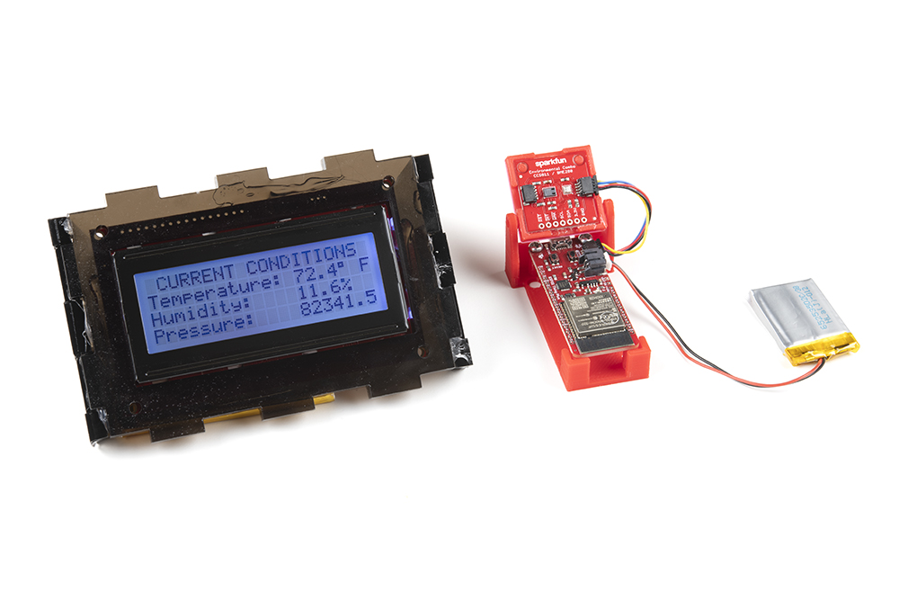
Once you've got the code loaded to both boards, powering them up will connect them, and you should see incoming data after only a few seconds.
Troubleshooting
If you aren't getting anything on the LCD display, or some other issue seems to have shown up, there are a few things you can check. Let's start by connecting the transmitting board (with the Environmental Sensor) to your computer with a USB cable, then opening up the Serial Monitor window. If the sensor is working properly and the WiFi module is sending the package, you should see something like this in the Serial Monitor:
Temperature in Fahrenheit: 74.46
Humidity: 22.21
Pressure: 84992.97
Sent with success
If the receiver isn't powered up, you'll also see:
Last Packet Send Status: Delivery Fail
If all is as it should be here, you can connect connect the receiving ESP32 to your computer, power up the transmitter with a battery or power supply, and check the results there. The Serial Monitor should be displaying the temperature, humidity, and pressure readings. If you're still having issues, reach out to our support team.
If your product is not working as you expected or you need technical assistance or information, head on over to the SparkFun Technical Assistance page for some initial troubleshooting.
If you don't find what you need there, the SparkFun Forums are a great place to find and ask for help. If this is your first visit, you'll need to create a Forum Account to search product forums and post questions.
Resources and Going Further
The focus of this project was simply to show you how to send data wirelessly. The great thing about the simplicity of this tutorial is that you could change out the sensor board we used for any one of many sensors with relative ease. You could also add another Qwiic sensor to this setup such as the SparkFun Ambient Light Sensor to add another data point which expands the dataset showing on your LCD. Looking through the hookup guides for the sensor you would like to use is a great place to start.
If you want to learn more about the SparkFun components used in this project, you can find that information in the hookup guides below.