Secure DIY Garage Door Opener
 QCPete
Integration
To engage the garage door, I opted to emulate what a human does (press the button on the wall inside). I opened up the wall-mounted controller and saw this:
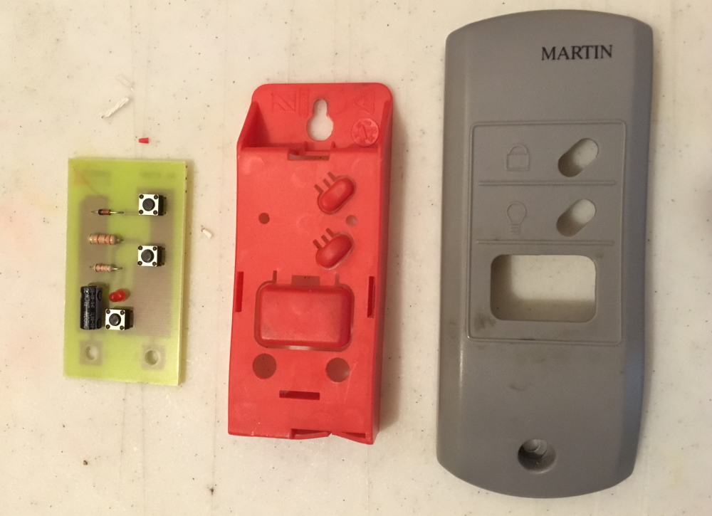
Aha! I recognize those mini push button switches.Upon further inspection, I saw that there are various passive components involved:
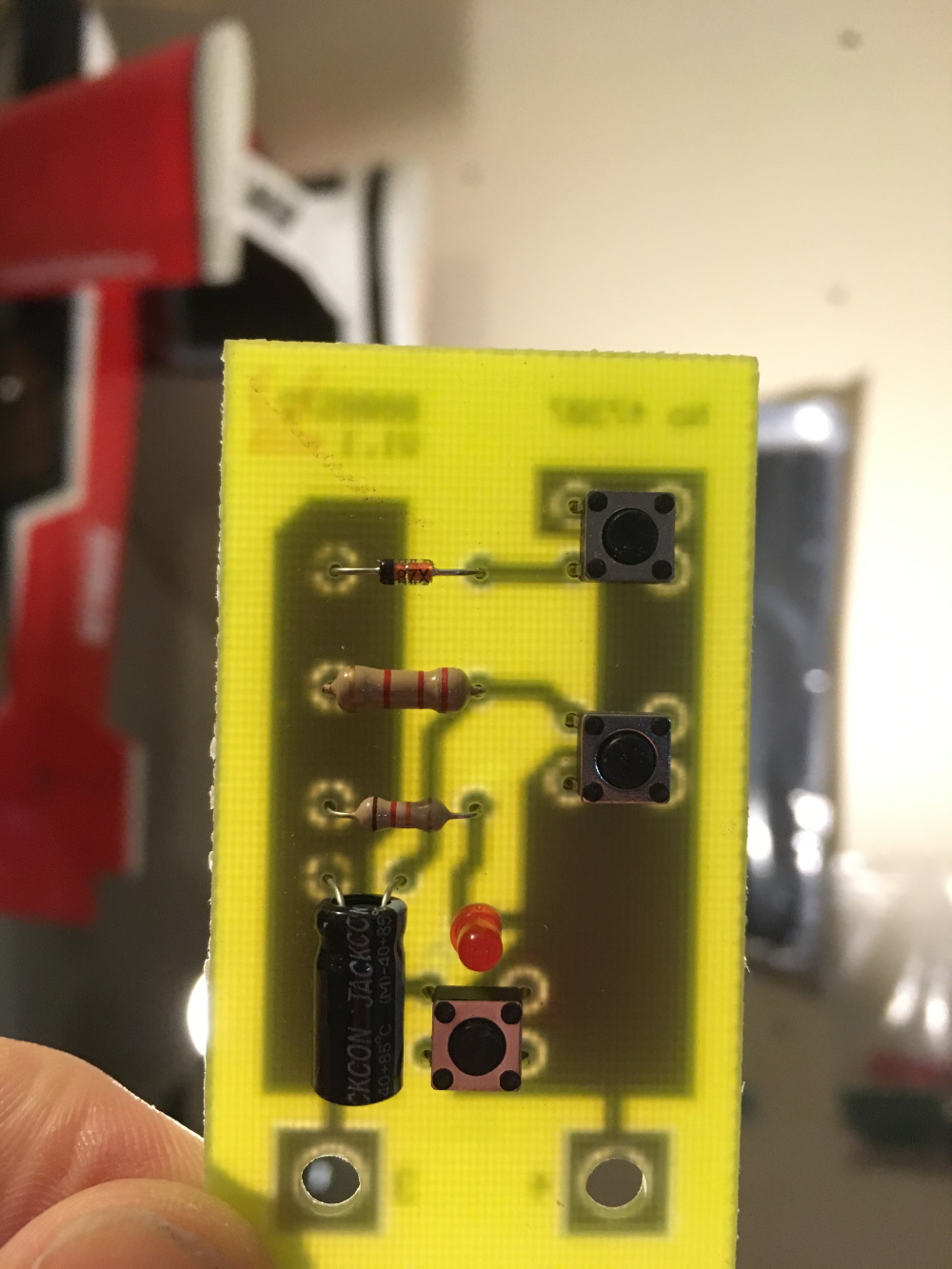
Pretty neat how they are able to get three button control from simply two wires. I wonder if there is an ADC involved? Or maybe some sort of pulsing and time sensitive digital reads? Maybe an AC signal? What do you think?
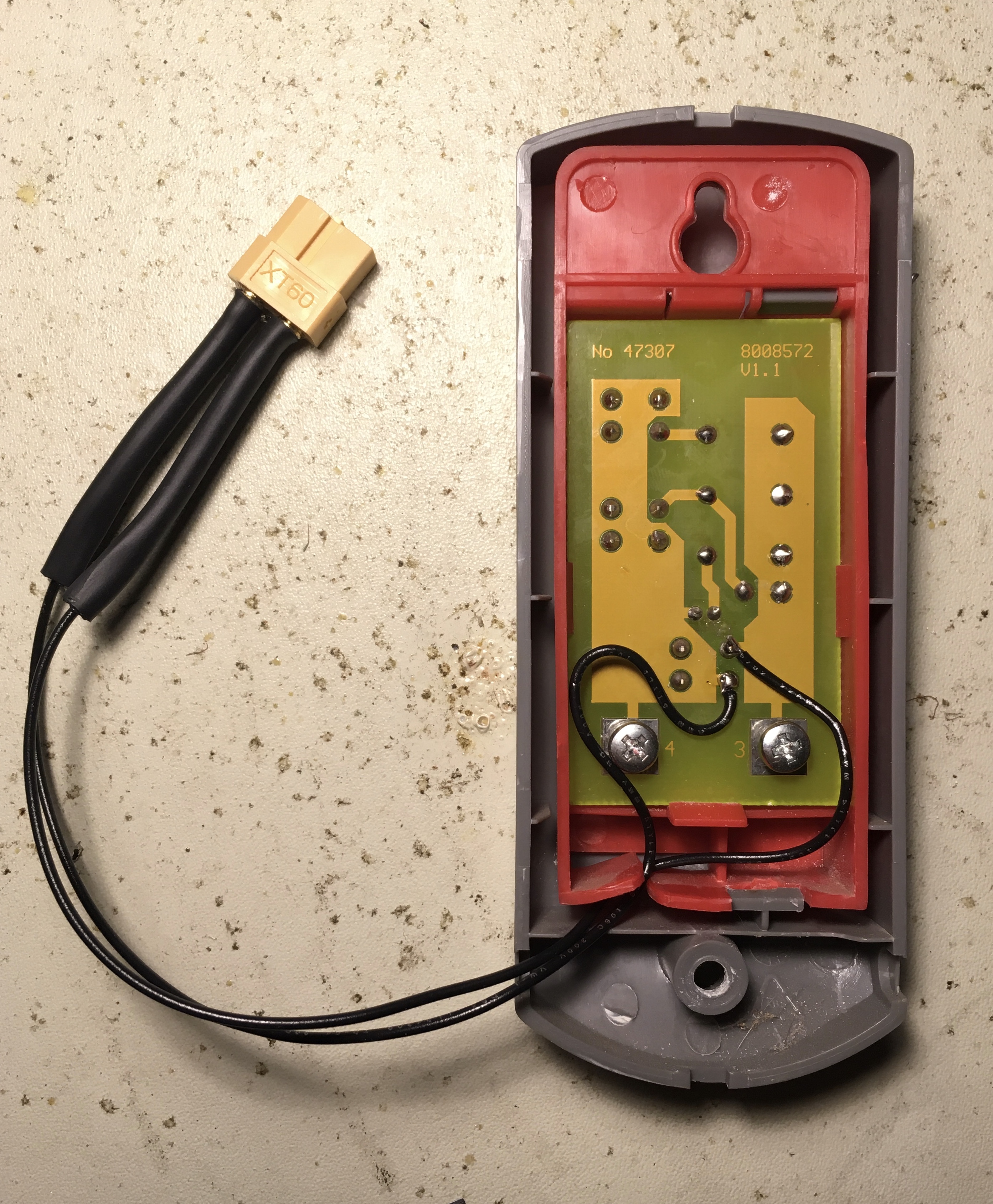
For this project, I was only concerned with the lower momentary switch (aka the "big button"). From looking at the circuit board with backlight as shown above, I was able to see that the lower button simply connects the two leads together directly without any extra passives involved. With this in mind, I decided to use a relay and run it in parallel with the switch. I used a SparkFun Qwiic Single Relay to engage this button from my Arduino. I know this is probably overkill for the amount of current this will ever see, but I liked that this solution would be very easy to connect/control using Qwiic and was a sure bet in emulating the button.
For the connection to the garage door wall-mounted button, I chose to open it up and solder to the connection points on either side of the button. After doing so, I actually realized that you could "tap" into the two wires out to the button anywhere in the line and potentially use the screw pin terminals on the relay for a solder-less connection point. Nevertheless, I used a couple XT-60 connectors on the lines, and this makes it pretty easy to take apart if necessary for re-programming.