RP2040 mikroBUS™ Development Board Hookup Guide
This Tutorial is Retired!
This tutorial covers concepts or technologies that are no longer current. It's still here for you to read and enjoy, but may not be as useful as our newest tutorials.
Hadware Assembly
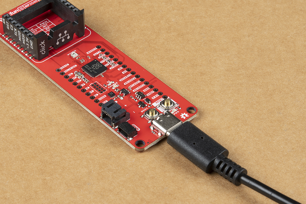
USB Programming
The USB connection is utilized for programming and serial communication. Users only need to plug their RP2040 mikroBUS™ development board into a computer using a USB-C cable.
BOOTSEL Mode
Users can enter BOOTSEL mode by holding down the BOOT button, when the USB connection is made to a computer. The board will remain in this mode until it power cycles (happens automatically after uploading a .uf2 firmware file) or the RESET button is pressed. The board will appear as a USB mass storage device under the name RPI-RP2.
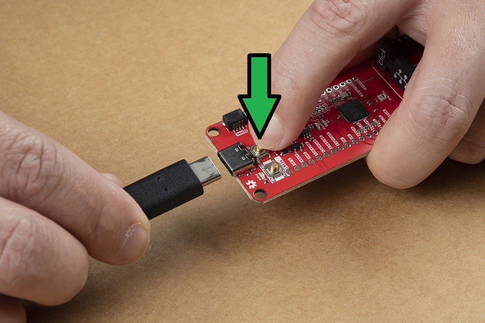
BOOT button to enter BOOTSEL mode on the RP2040 mikroBUS™ development board. (Click to enlarge) Battery
For remote applications, the RP2040 Thing Plus can be powered through its 2-pin JST battery connector. Additionally, users may be interested in utilizing a solar panel and USB-C cable to recharge their battery.
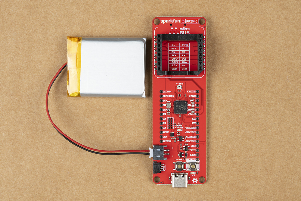
The RP2040 mikroBUS™ development board with a battery attached. (Click to enlarge)
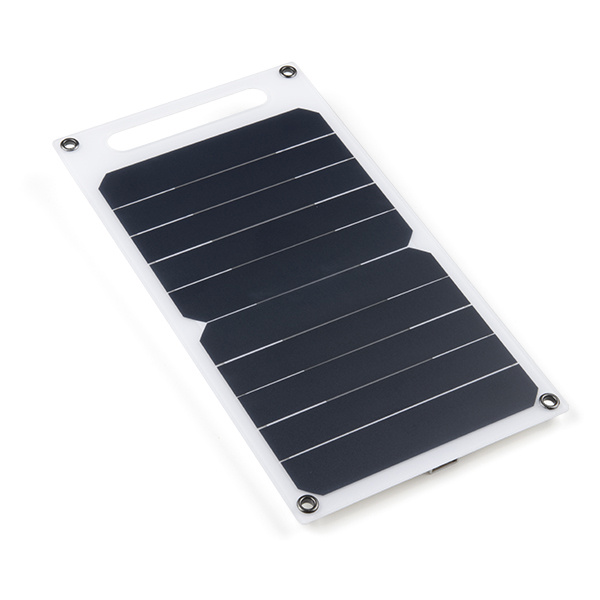
Solar Panel Charger - 10W
PRT-16835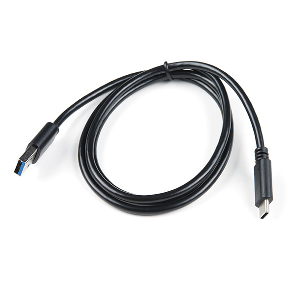
Note: DO NOT remove batteries by pulling on their wires. Instead, it is recommended that pair of dikes (i.e. diagonal wire cutters), pliers, or tweezers be used to pull on the JST connector housing, to avoid damaging the battery wiring.
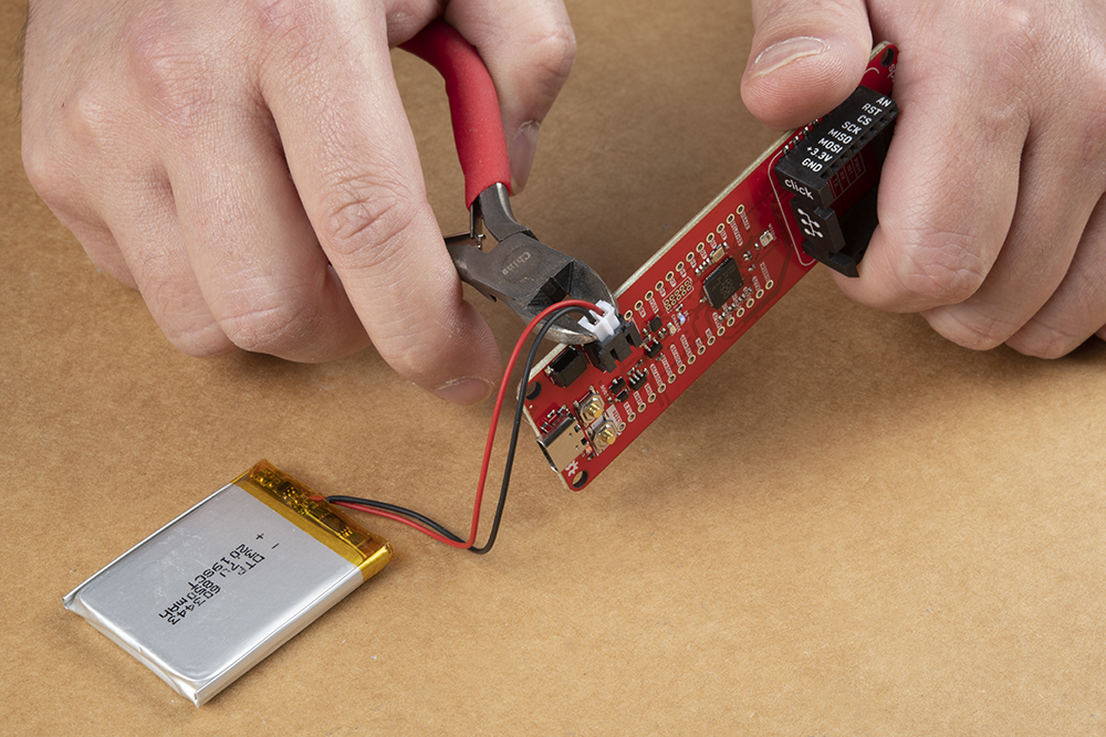
Using a pair of dikes to disconnect a battery. (Click to enlarge)
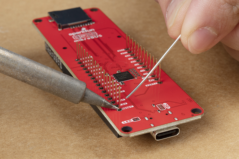
Headers
The pins for the RP2040 mikroBUS™ development board are broken out to 0.1"-spaced pins on the outer edges of the board. When selecting headers, be sure you are aware of the functionality you need. If you have never soldered before or need a quick refresher, check out our How to Solder: Through-Hole Soldering guide.
The Feather Stackable Header Kit is a great option as it allows users to stack shields (w/ Feather footprint) or it can be placed on the a breadboard; while, the pins are still accessible from the female/male headers.
mikroBUS™ Socket
The RP2040 mikroBUS™ development board has a mikroBUS™ Socket, where a Click board™ can be inserted.
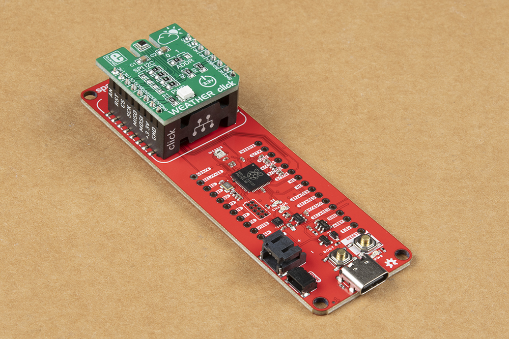
Note: To remove a Click board™, slowly and carefully wiggle it out of the mikroBUS™ socket to avoid bending the header pins on your Click board™.
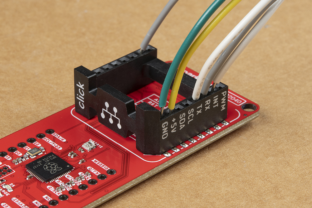
The header also allows users to connect jumper wires to devices that may not have the mikroBUS™ pin layout to interface with.
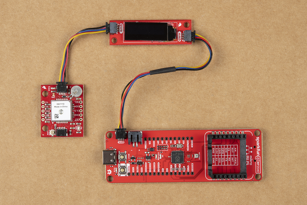
Qwiic Devices
The Qwiic system allows users to effortlessly prototype with a Qwiic compatible I2C device without soldering. Users can attach any Qwiic compatible sensor or board, with just a Qwiic cable. (*The example below, is for demonstration purposes and is not pertinent to the board functionality or this tutorial.)