RFM69HCW Hookup Guide
 MikeGrusin
Hardware Overview
Frequency
The RFM69HCW transmits in the ISM (Industry Scientific and Medical) band, a set of frequencies set aside for low-power, short-range, license-free radios.
SparkFun sells two versions of the RFM69HCW, a 915 MHz version and a 434 MHz version. These frequencies are legal in different areas: very roughly, 915 MHz is for use in the Americas and Australia, and the 434 MHz version is for use in Europe, Asia and Africa. The actual regulations are a bit of a patchwork, so check your local regulations for other areas.
Range
How far will the signal reach? Outside with few obstructions, you should be able to get a solid link for hundreds of meters. Indoors we've seen it work for over 50 meters through multiple walls.
The RFM69HCW is capable of transmitting at up to 100 mW and up to 300 kb/s, but you can change both of those values to fit your application. For example, you can maximize range by increasing the transmit power and reducing the data rate. Or you can reduce both for short-range wireless sensor networks that sip battery power.
Board Pinout
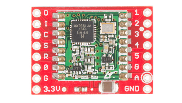
The RFM69HCW Breakout Board gives you access to all the pins on the RFM69HCW, but in the majority of cases you'll only need seven of them. Here's an overview of the pins we'll be using:
Power
| Board Label | Name | Function |
| 3.3V | Power | 3.3V power supply (at least 130 mA, see below) |
| G / GND | Ground | Power ground |
Data
| Board Label | Name | Function |
| O / MISO | Master In Slave Out | Data from RFM69HCW to microcontroller |
| I / MOSI | Master Out Slave In | Data from microcontroller to RFM69HCW |
| C / SCK | Serial ClocK | Clock signal from microcontroller to RFM69HCW |
| S / NSS | Slave Select | Select signal from microcontroller to RFM69HCW |
| 0 / DIO0 | Digital I/O 0 RX interrupt |
Received data ready interrupt signal from RFM69HCW to microcontroller |
Antenna
| Board Label | Name | Function |
| A / ANT | Antenna | Wire antenna, see the next page for details |
| G / GND | Ground | Antenna ground (same as power ground) (You can use either G pin adjacent to the antenna pin) |
The unused pins labeled 1 to 5 have functions that we won't be using. See the RFM69HCW datasheet for more information.
Power requirements
The RFM69HCW will run on voltages from 1.8V to 3.6V, and can draw up to 130mA of current when it's transmitting.
The easiest way to use this board is to connect it directly to a 3.3V Arduino such as the 3.3V Arduino Pro. However, you can connect it to a 5V Arduino if you use a logic-level translator. See the diagram in the Hardware Connections section.
In this tutorial we'll use two 3.3V Arduino Pros powered by the "Beefy 3" FTDI basics. We're using the Beefy 3 FTDI because it can provide up to 500mA, as opposed to the standard FTDI which can only provide 50mA.
Incidentally, the RFM69HCW uses 16mA when it's in receive mode, and it has several sleep options that use less than that.