RFM69HCW Hookup Guide
 MikeGrusin
Hardware Connections
Connecting the RFM69HCW to an Arduino
There are lots of ways to connect boards together. In this tutorial, we're going to solder Male Breakaway Headers to the RFM69HCW board, solder Female Headers to the Arduino Pro, and use M/F Jumper Wires to connect everything together. Of course, you can use whatever wiring methods you wish.
Step 1: Solder male header onto the RFM69HCW:
Break off one 8-pin length of Male Breakaway Header, and solder it to the "O I C S R 0 G 3.3V" side of the RFM69HCW board. You can solder it to the top or bottom, your choice.
Repeat for the second RFM69HCW.
Step 2: Solder female headers onto the Arduino Pro:
Solder the four Female Headers to the Arduino Pro. They should stick out of the top of the board.
Repeat for the second Arduino Pro.
Step 3: Use M/F jumper wires to connect the RFM69HCW to the Arduino Pro:
Different Arduino models use different pins for the SPI port. See the following table for the proper connections:
| RFM69HCW pin | 328 (Pro/Mini/Redboard/Uno) | Mega | 32U4 (Leonardo/Due/Pro Micro) |
| O / MISO | 12 or ICSP-1 | 50 or ICSP-1 | 14 or ICSP-1 |
| I / MOSI | 11 or ICSP-4 | 51 or ICSP-4 | 16 or ICSP-4 |
| C / SCK | 13 or ICSP-3 | 52 or ICSP-3 | 15 or ICSP-3 |
| S / NSS | 10 | 53 | 10 |
| 0 / DIO0 | 2 | 2 | 3 |
| 3.3V | 3.3V (labeled "VCC" on Pro/Mini) | ||
| G / GND | GND | ||
| A / ANT | See the next section for antenna information | ||
If you use the ICSP header for your SPI connection, note the pin numbering:
| 1 | 2 |
| 3 | 4 |
| 5 | 6 |
Wiring Diagrams
3.3V Arduinos
As we've mentioned, it's easiest to connect the RFM69HCW directly to a 3.3V Arduino such as the Arduino Pro:
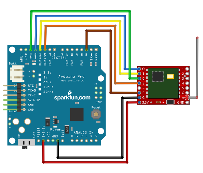
Be sure that you're powering your Arduino with a "Beefy 3" FTDI board, a wall-wart, or a Lipo battery. A normal FTDI Basic won't be able to supply enough current to run the RFM69HCW.
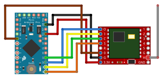
A 3.3V Arduino Pro Mini is also a great choice, since both boards are very small:
5V Arduinos
You can connect the RFM69HCW to a 5V Arduino, such as our RedBoard, if you use a logic level translator between them. The translator translates the Arduino's 5V signals to 3.3V signals, which won't damage the RFM69HCW:
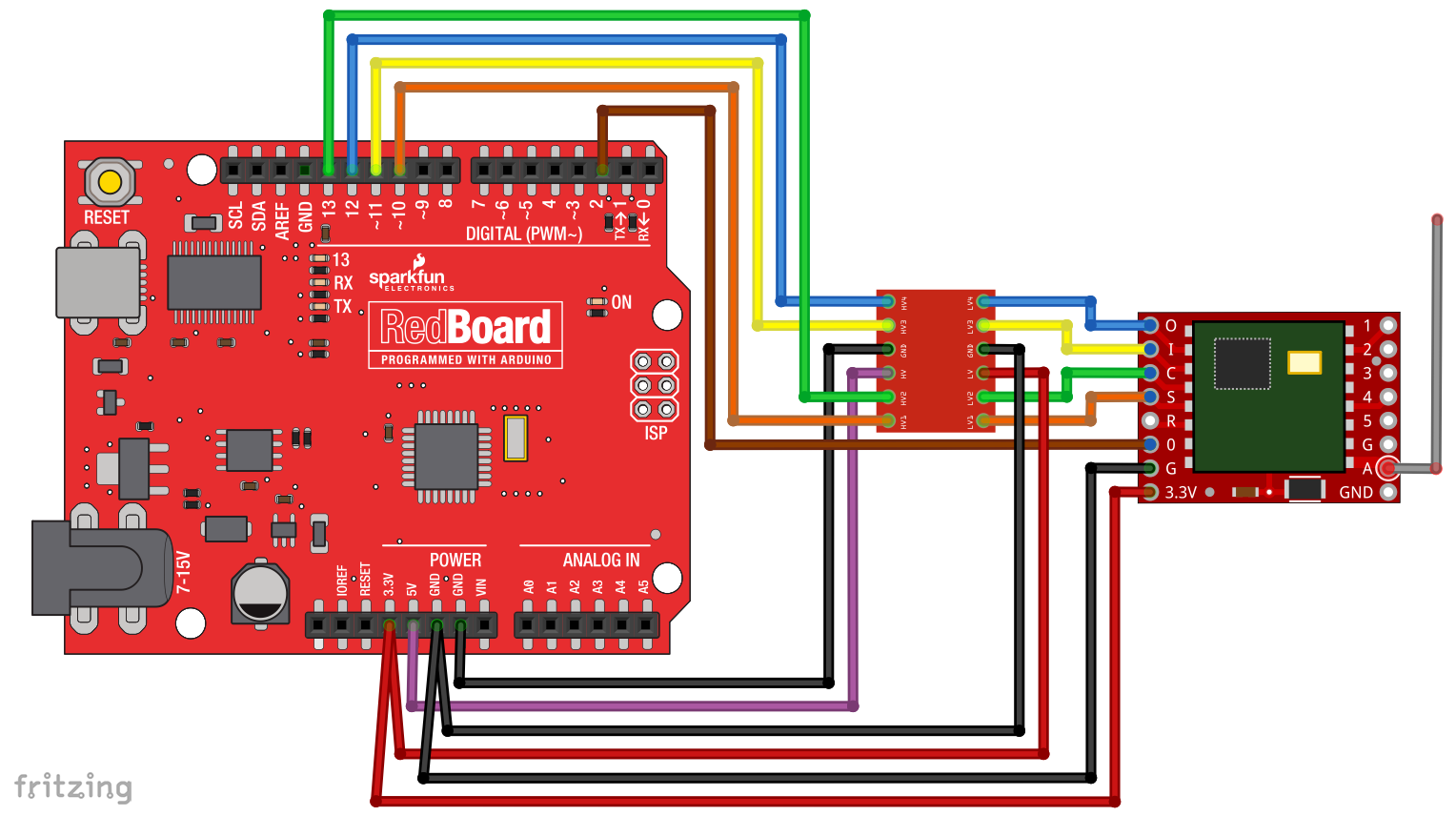
5V Arduinos have both a 5V and a 3.3V supply. Here we're using the 5V supply (purple wire) to power the high-voltage side of the logic level translator, and the 3.3V supply (red wire) to power both the RFM69HCW and the low-voltage side of the logic level translator. Remember to never connect 5V to the RFM69HCW.
External Status LED
One more thing: the example code we'll get to in a few pages blinks a LED to indicate when data is sent or received.
Unfortunately we can't use the Arduino's built-in LED for this, because that port (D13) is also used by the SPI port's SCK line. We use the SPI port to communicate with the RFM69HCW, so this LED will be on a lot of the time.
To make up for this, the example code is written so you can stick any old LED into your Arduino, with the long (positive) lead in D9, and the short (negative) lead in D8.
This step is optional, and not required for the normal operation of the RFM69HCW.
(Normally we would want to include a current-limiting resistor in series with the LED to prevent it from being burned out. But for simplicity, we'll rely on the current-limiting built into the Arduino's I/O ports, along with the fact that we'll only be turning it on for very brief periods to indicate packets sent or received.)