RFID Beginners Tutorial
 Brandon J. Williams
Introduction
In this tutorial we'll show you how to make a remote "clock punch" that logs time, location, and identification.
RFID is as magic as waving a card in front of a little black box and doors open for all to pass. This technology is so versatile that it was projected in 2017 to support a $31.42 billion market by 2023. We’ve enjoyed RFID tech as much as the next and we want to share it with you. In this tutorial we’ll touch on some key topics of the technology. Then we’ll work on making a remote work clock punch that can log time, location, and identification. Who knows, maybe you’ll find your own magic in RFID as well.
What Is RFID?
In simple terms, RFID Technology is a method of wireless communication between two (or more) electrical components. There is a reader that can emit a signal and passively reads incoming signals. Tags are devices that contain identification or other information. They come in two types, passive or active. Active tags have their own power source to actively transmit their contained information. Passive tags are ‘powered’ through radiated signals from the reader to transmit unique information. Either way it boils down to two devices yelling at each other like two cranky people. This transmission is how we’ll pass this information to our microcontroller to log our "in’s and out’s".
Required Materials
To follow along with this tutorial, you will need the following materials. You may not need everything though depending on what you have. Add it to your cart, read through the guide, and adjust the cart as necessary.
Suggested Reading
Before going further, brave adventurer, please feel free to brush up on other tutorials and content that will help you on your journey.
GPS Basics
I2C
Serial Terminal Basics
RFID Basics
SparkFun Qwiic RFID-IDXXLA Hookup Guide
SparkFun GPS Breakout (ZOE-M8Q and SAM-M8Q) Hookup Guide
Displaying Your Coordinates with a GPS Module
Hookup Guide for the SparkFun RedBoard Artemis Nano
| Qwiic Connect System |
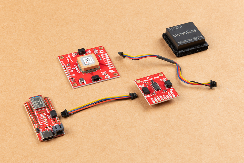
Hardware Overview
We'll be using the Artemis Nano to read the RFID tags and GPS modules. We will be using Arduino to program the Artemis nano. For more information about each component, click on the links to the product pages.
Artemis Nano
"With 1MB flash and 384k RAM you'll have plenty of room for your sketches. The Artemis module runs at 48MHz with a 96MHz turbo mode available and with Bluetooth to boot! The SparkFun Artemis Nano is an incredibly flexible device for a small footprint..."
Qwiic RFID Reader
"The SparkFun RFID Qwiic Kit is a simple, yet all-in-one I2C based RFID starting point for the ID-3LA, ID-12LA, and ID-20LA readers. Simply plug a reader into the headers and use a Qwiic cable to connect to any Qwiic enabled development board, then scan your 125kHz ID tag and the unique 32-bit ID will be shown on the screen."
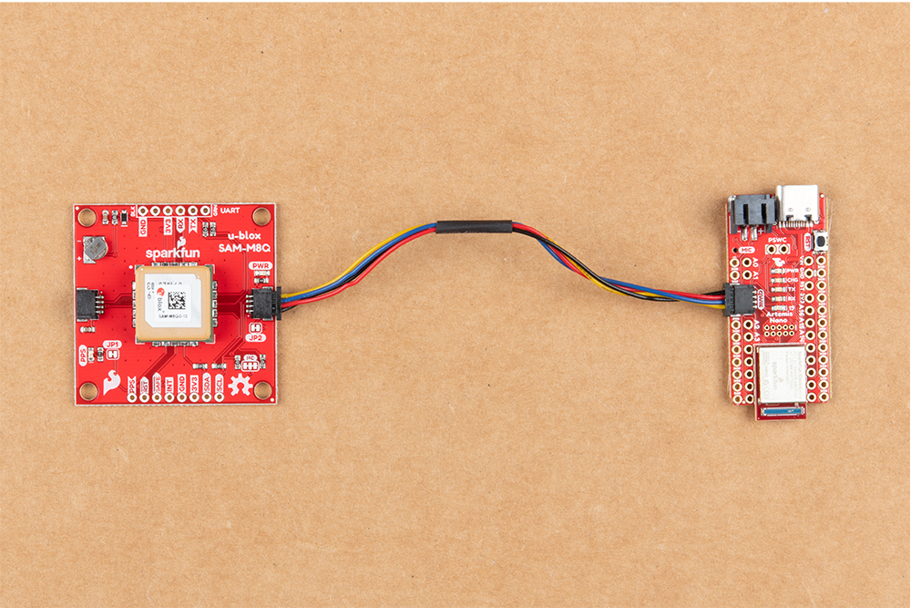
SAM-M8Q - Chip Antenna
"The SparkFun SAM-M8Q GPS Breakout is a high quality, GPS board with equally impressive configuration options. The SAM-M8Q is a 72-channel GNSS receiver, meaning it can receive signals from the GPS, GLONASS, and Galileo constellations. This increases precision and decreases lock time and thanks to the onboard rechargable battery, you'll have backup power enabling the GPS to get a hot lock within seconds!"
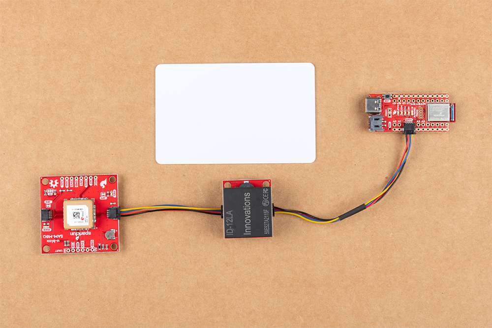
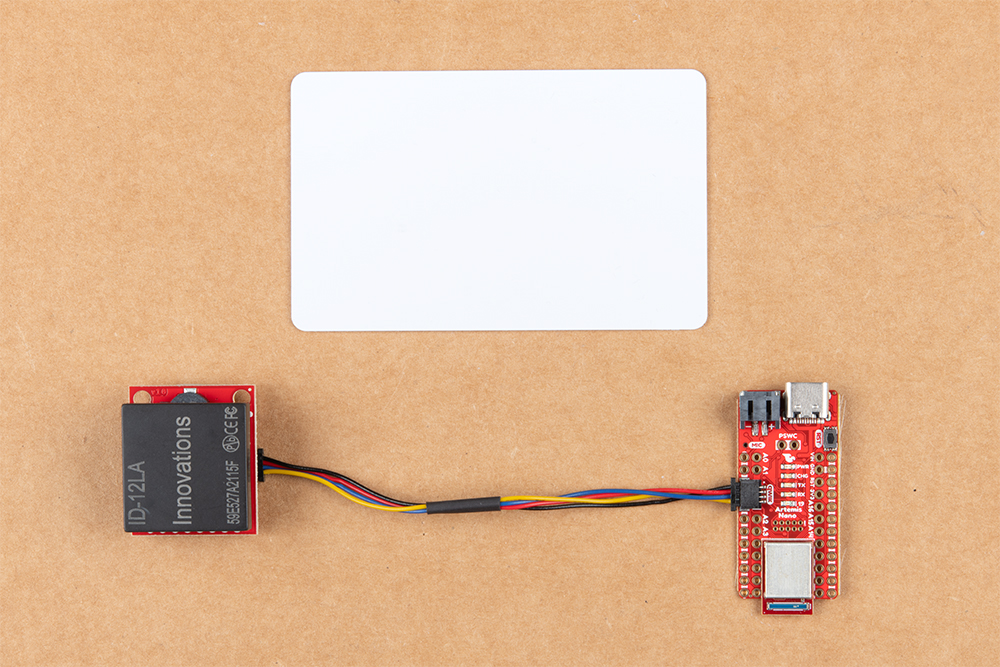
Hardware Hookup
As far as the hardware is concerned, we’re going to lean hard on the Qwiic ecosystem. This ecosystem allows us to easily connect devices together without needing to solder. No mess, no fuss!
Software
If this is your first time using Arduino, please review our tutorial on installing the Arduino IDE. If you have not previously installed an Arduino library, please check out our installation guide.
Our final code will be a mash up of two basic examples for our components. We’ll take a quick look at each part of the examples that we’ll use and talk about the main points.
Qwiic RFID Reader
The Qwiic RFID library will give you the full functionality of the Qwiic RFID ID-XXLA without the hub bub of the I²C data transactions. Also included are examples codes to demonstrate the full functionality of the library. You can click the link below to download the file directly and install it manually, or navigate through the Arduino Library Manager by searching SparkFun Qwiic RFID. You can also go the GitHub page and get download it from there.
In the Read_Tag_Basics example, the reader logs all tags that are recognized in a memory buffer. We read the buffer and clear it for a new read. We see that functionality below:
language:c
serialInput = Serial.read();
if (serialInput == 49){   // "1" on your keyboard is 49 in ASCII
  tag = myRfid.getTag();
  Serial.print("Tag ID: ");
  Serial.print(tag);
  scanTime = myRfid.getPrecReqTime();
  // If this time is too precise try:
  // long time = myRfid.getReqTime();
  Serial.print(" Scan Time: ");
  Serial.println(scanTime);
}
Serial.read(); reads the buffer into the micro-controller's memory and clears the reader's buffer for another swipe. The tag is printed in the serial output along with the scan time. What we need to take away from this is the Serial.read(); and myRfid.getTag();.
SAM-M8Q GPS Module
#include "SparkFun_Ublox_Arduino_Library.h" to #include "SparkFun_u-blox_GNSS_Arduino_Library.h".
The SparkFun U-blox Arduino library can be downloaded with the Arduino library manager by searching 'SparkFun Ublox' or you can grab the zip here from the GitHub repository:
Using SparkFun’s u-blox Arduino Library and Example2_NMEAParsing.ino, we’ll get our GPS coordinates and time. If you look closely at the code below, you’ll notice that something is missing:
language:c
long latitude_mdeg = nmea.getLatitude();
long longitude_mdeg = nmea.getLongitude();

Serial.print("Latitude (deg): ");
Serial.println(latitude_mdeg / 1000000., 6);
Serial.print("Longitude (deg): ");
Serial.println(longitude_mdeg / 1000000., 6);
We’re missing functions to get time. However, if we look at the u-blox library header file we can see the following functions that we’ll add in to the final code similarly to how the latitude and longitude functions are called in the example:
language:c
uint16_t getYear(uint16_t maxWait = getPVTmaxWait);
uint8_t getMonth(uint16_t maxWait = getPVTmaxWait);
uint8_t getDay(uint16_t maxWait = getPVTmaxWait);
uint8_t getHour(uint16_t maxWait = getPVTmaxWait);
uint8_t getMinute(uint16_t maxWait = getPVTmaxWait);
uint8_t getSecond(uint16_t maxWait = getPVTmaxWait);
These functions will give us time. Now let's combine all our parts. The full code is below:
language:c
/******************************************************************************
Remote Work Punch Clock
brandon.williams@sparkfun.com
May 6, 2019

Description When a card is read then the GPS coordinates and time are read from
    the GPS module.

Development environment specifics:
Arduino IDE 1.8.12 (or most recent)

Board Definition Packages (or most recent):
  SparkFun Apollo3 Boards           1.1.1
  MicroNMEA                         2.0.1
  SparkFun_Qwiic_Rfid.h             1.1.6
  SparkFun_u-blox_GNSS_Arduino_Library    2.0.2
******************************************************************************/


#include <MicroNMEA.h>

#include <SparkFun_Qwiic_Rfid.h>

#include <SparkFun_u-blox_GNSS_Arduino_Library.h>//http://librarymanager/All#SparkFun_u-blox_GNSS


#define RFID_ADDR 0x7D // Default Qwiic RFID I2C address

// Variables and Constants
      /*GPS*/
SFE_UBLOX_GNSS myGNSS;
char nmeaBuffer[100];
MicroNMEA nmea(nmeaBuffer, sizeof(nmeaBuffer));
      /*RFID*/
Qwiic_Rfid myRFID(RFID_ADDR);
String tag;
float scanTime;
int serialInput;

void setup() {

  Wire.begin();
  //Disable Serial after confirming setup works
  Serial.begin(115200);

  /*Qwiic RFID begin*/
  if(myRFID.begin()== false){
    Serial.println("Could not communicate with Qwiic RFID!");
    while(1);
  }

}

void loop() {

  /*RFID loop code*/
  tag = myRFID.getTag();

  /* Empty string is returned if no tag is present,
   * wait till a valid ID string is returned.
   */
    if(myGNSS.begin() != false){
      if(tag.length() != 6){
        Serial.print("Tag ID: ");
        Serial.println(tag);

        /*GPS loop code*/
        myGNSS.checkUblox(); //See if new data is available. Process bytes as they come in.

        if(nmea.isValid() == true){
          if(nmea.getNumSatellites() != 0){
            long latitude_mdeg = nmea.getLatitude();
            long longitude_mdeg = nmea.getLongitude();
            uint16_t dateYear =  nmea.getYear();
            uint8_t dateMonth = nmea.getMonth();
            uint8_t dateDay = nmea.getDay();
            uint8_t dateHour = nmea.getHour();
            uint8_t dateMin = nmea.getMinute();
            uint8_t dateSec = nmea.getSecond();

            //Print Coordinates
            Serial.print("Latitude (deg): ");
            Serial.println(latitude_mdeg / 1000000., 6);
            Serial.print("Longitude (deg): ");
            Serial.println(longitude_mdeg / 1000000., 6);

            //Print Time
            Serial.print("Date and Time: ");
            Serial.print(dateMonth);
            Serial.print("-");
            Serial.print(dateDay);
            Serial.print("-");
            Serial.print(dateYear);
            Serial.print(" @ ");
            Serial.print(dateHour);
            Serial.print(":");
            Serial.print(dateMin);
            Serial.print(":");
            Serial.println(dateSec);
          }
        }
        else{
          Serial.print("No Fix - ");
          Serial.print("Num. satellites: ");
          Serial.println(nmea.getNumSatellites());
        }
      }
      delay(500);
    }
}

//This function gets called from the SparkFun Ublox Arduino Library
//As each NMEA character comes in you can specify what to do with it
//Useful for passing to other libraries like tinyGPS, MicroNMEA, or even
//a buffer, radio, etc.
void SFE_UBLOX_GNSS::processNMEA(char incoming)
{
  //Take the incoming char from the Ublox I2C port and pass it on to the MicroNMEA lib
  //for sentence cracking
  nmea.process(incoming);
}
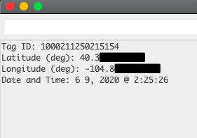
When we swipe a card over the scanner then we should get something like below:
Troubleshooting
If your product is not working as you expected or you need technical assistance or information, head on over to the SparkFun Technical Assistance page for some initial troubleshooting.
If you don't find what you need there, the SparkFun Forums are a great place to find and ask for help. If this is your first visit, you'll need to create a Forum Account to search product forums and post questions.
Resources and Going Further
This tutorial is just a first step into making a larger RFID project. Stay tuned for a more advanced tutorial to expand beyond just reading data in a serial monitor.
In the meantime, please feel free to visit more RFID tutorials and learn new skils:
SparkFun RFID Starter Kit Hookup Guide
Build a Qwiic Jukebox that is Toddler Approved!
Qwiic Dynamic NFC/RFID Tag Hookup Guide
How To Take Multiple RFID Readings Simultaneously