RETIRED - Using the Logic Level Converter
This Tutorial is Retired!
This tutorial covers concepts or technologies that are no longer current. It's still here for you to read and enjoy, but may not be as useful as our newest tutorials.
View the updated tutorial: Bi-Directional Logic Level Converter Hookup Guide
 jimblom
Meet the LLC
Electronics can be maddening sometimes! Like when you want to hookup that totally groundbreaking, awesome, must-have sensor, which has a maximum input voltage of 3.3V, to an Arduino running at 5V. Ack! Connecting these devices can be a problem -- applying an out-of-range voltage to a device's I/O pin can overstress it and eventually lead to failure. This is a dilemma so common we designed a simple PCB assembly to make interfacing devices a little easier: the Logic Level Converter.
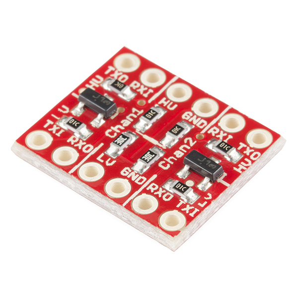
Logic Level Converter
BOB-11978The LLC can convert up to four I/O lines from a high-to-low and low-to-high. Two inputs convert from low voltage to a higher, and the other two line convert bi-directionally (high-to-low and/or low-to-high).
Covered In This Tutorial
In this tutorial we'll take an in-depth look at the Logic Level Converter. Check into it's schematic. Explain what each pin on the board does, and where it goes. Then we'll go over some example hook-ups, explaining how you might use the board in a serial interface, or SPI, or even I2C.
Suggested Reading
- Logic Levels
- Voltage Dividers
- How to Use a Breadboard
- What is an Arduino?
- How to Solder
- Working with Wire