RETIRED - Using the Logic Level Converter
This Tutorial is Retired!
This tutorial covers concepts or technologies that are no longer current. It's still here for you to read and enjoy, but may not be as useful as our newest tutorials.
View the updated tutorial: Bi-Directional Logic Level Converter Hookup Guide
 jimblom
Hookup Examples
Assembly
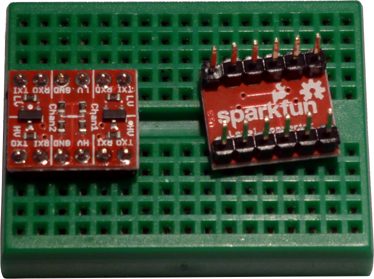
Before you can plug the converter into your system, you'll need to solder something into it. There are a lot of options here. You could solder straight male headers in, and plug it right into a breadboard. Or perhaps you want to solder wires directly into it. Pick an assembly method that melds with how you intend to use the board.
Using the LLC for Serial
Converting voltages between serial devices is the part the LLC was born to play -- that's why it has the 'RX' and 'TX' labels. Lets say, for example, you have an Electric Imp -- which has a maximum voltage of 3.3V -- plugged into a Electric Imp Breakout Board and connected up to a standard Arduino Uno. Here's how you might wire the two together, using an LLC to convert logic levels:
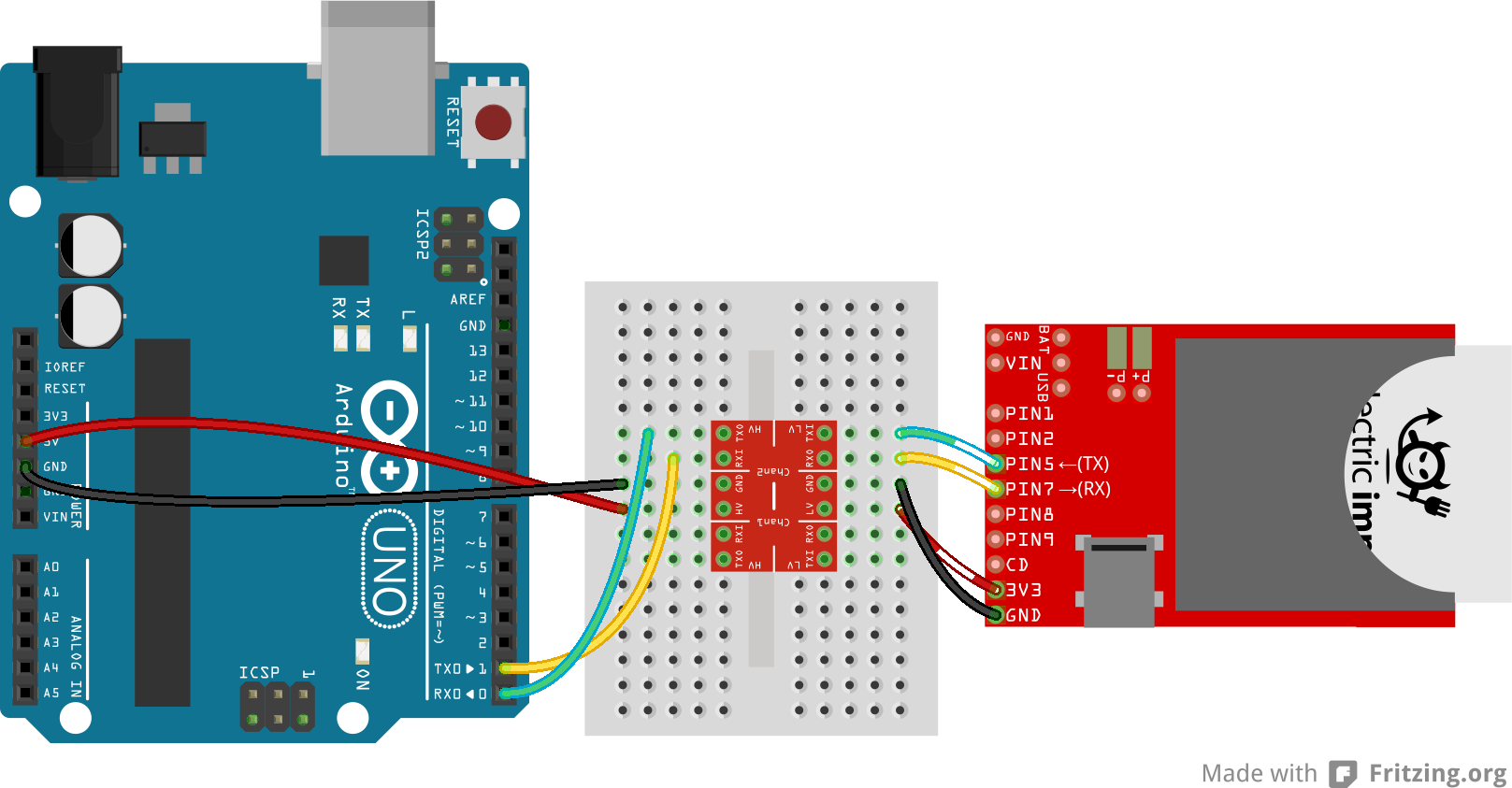
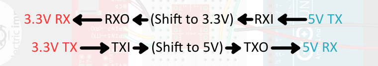
All of these 'RX', 'RXI', 'RXO', and even 'RX0' labels can get confusing. Remember 'I' stands for Input and 'O' stands for Output. If the Electric Imp sends a signal out of it's 'TX' pin it'll go into the 'TXI' pin on the LLC, get shifted up to 5V and come out the 'TXO' pin, and finally run into 'RX' on the Arduino.
Using the LLC for SPI
A standard SPI connection requires four wires -- MOSI, MISO, SCLK, and CS -- so we'll need to use every pin on the LLC to shift this interface.
Let's say, for example, you want to hook up an Arduino (again, running at 5V) to an ADXL345 Breakout Board. The ADXL345 has an operating range of 2.0-3.6V, so we'll run it at 3.3V. Here's how you might connect the two over an SPI interface, with an LLC in between:
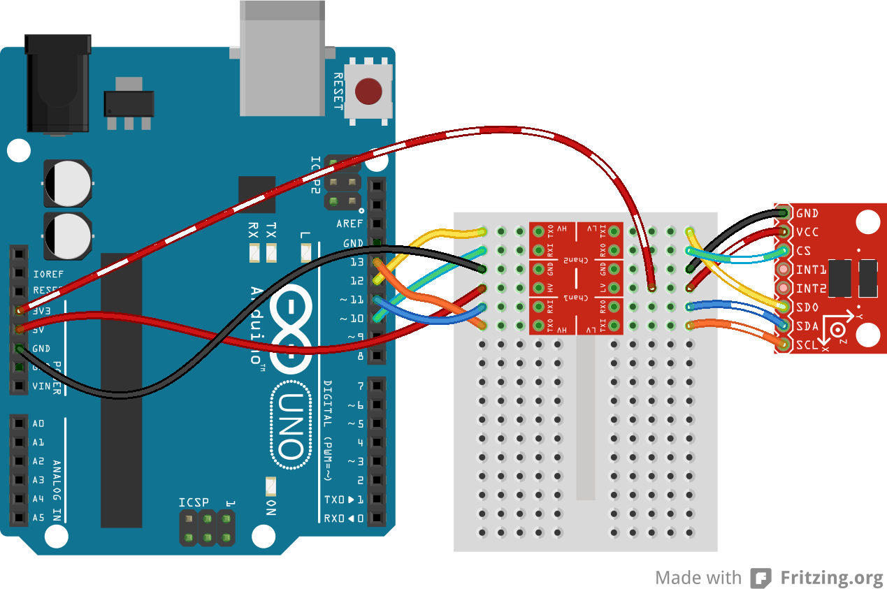
This hookup is weird because three wires are inputs to the ADXL345 and only one is an output. We can take advantage of the bi-directional ability of the TXI-to-TXO line to pass a signal (SCL in this example) from the high side to the low side.
Using the LLC for I2C
I2C is another weird situation where both wires -- SDA and SCL -- need to be bi-directional. So to use the LLC for an I2C interface, we need to take advantage of both bi-directional shifters on the board.
Let's switch it up even further here. What if we had a 3.3V microcontroller trying to communicate with a 5V sensor. How about an Arduino Due trying to get the time from a 5V-only Real-Time Clock Module. Here's how we might hook the two up using an LLC:
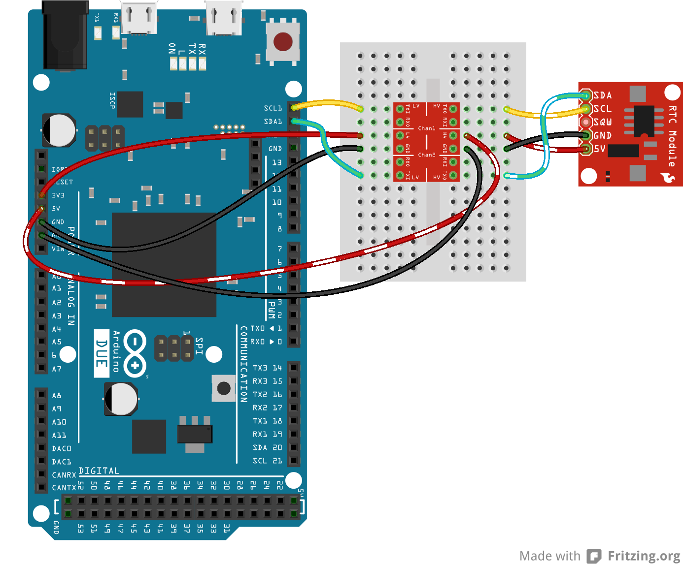
For I2C, this hookup is the same regardless of which of the two devices (master or slave) is low-voltage. Each wire should pass through a TXI-to-TXO converter.