RETIRED - Pi Wedge Hookup Guide
This Tutorial is Retired!
This tutorial covers concepts or technologies that are no longer current. It's still here for you to read and enjoy, but may not be as useful as our newest tutorials.
View the updated tutorial: RETIRED - Pi Wedge B+ Hookup Guide
 Byron J.
Power And Logic Levels
Power
Understanding the Pi's power supply is critical to using it successfully.
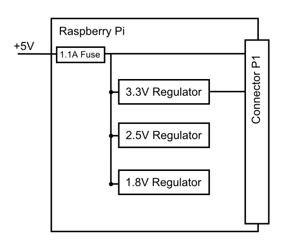
Consulting the Raspberry Pi schematic, we see that 5V comes into the the board via connector S1 - it's a micro USB connector, but only the power and ground pins are connected. The 5V coming from this connector passes through a fuse, then continues around the board without any further regulation. The 5V connections on the Pi Wedge come straight from this line.
On the Pi, the 5V goes to a set of daisychained regulators that further reduce it to 3.3v, 2.5V and 1.8V. The regulated 3.3V is present on the I/O connector.
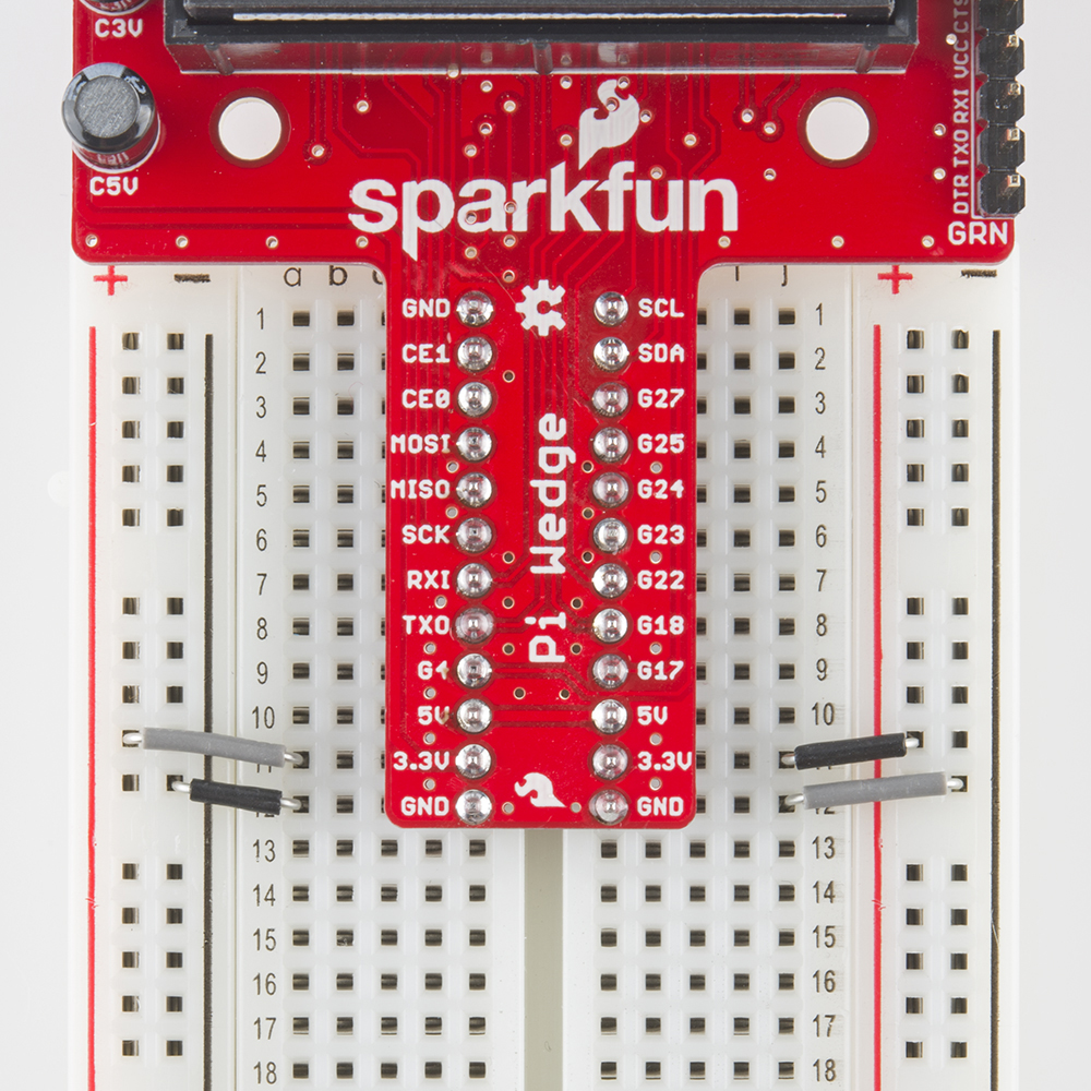
To power small circuits on your breadboard, you can run jumpers from the 5V or 3.3V and Ground pins on the wedge to the power rails on the breadboard.
Be aware that there's not a lot of juice available from the Pi. The Pi foundation states that the max draw from the 3.3V pins is 50 mA. In our experience, that's not a lot. When we built a display with a string of alphanumeric LED modules, we reached the point that turning on too many LED segments caused the CPU to reboot.
Similarly, the current available on the 5V pins is constrained by the fuse and limits of the attached USB port.
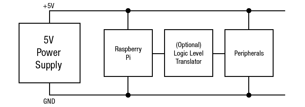
If you want to drive a lot of circuitry from a Pi, you'll need to use a more robust power distribution scheme. One example would be to use an external power supply, connected directly to each portion of the system. For peripherals that use 5V logic, it would also involve logic level translation.
Logic Levels
The Pi uses 3.3V logic levels, which are not 5V tolerant. Many peripheral devices are capable of running at 3.3V, but in the case that you need to interface with 5V devices, use a level shifter, such as the TXB0104 breakout.
Communications
Finally, the signals on the 6-pin FTDI header are also limited to 3.3v logic levels. Be sure to use it with a 3.3V FTDI module, and not a 5V one.